(a) Foundation of composite elements
The composite elements, in the case of spread footing foundation, require one unified spread footing.
In order to comprehend the reinforcement of composite elements, the following sections regard the reinforcement of the unified footings used in the two characteristic examples of paragraph 3.3
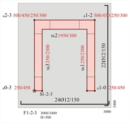
The three shear walls of the elevator constitute one element (elevator core) whose foundation is composed of a spread footing reinforced by a grate of rebars placed at its lower surface.
 Unified spread footing of an elevator core
 Unified spread footing of an elevator core
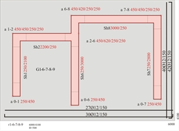
 Unified spread footing of a staircase area
 Unified spread footing of a staircase area
In the case where the foundation of the staircase is composed of a unified spread footing, due to its extremely extensive surface, it is required to place a double reinforcement grate (at the upper and lower surface).
The vehicle ramp on ground is an extensive load bearing element which at the same time con-stitutes its self-foundation. As in every other foundation, the soil quality has a fundamental im-portance. Most of the times, the ramp foundation is formed, at least partially, with compacted fill.
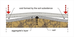
Most of the times, no matter how much effort has been put into the proper compaction of the soil, there is uncertainty about its proper behavior in the future, as shown in the following fig-ures.
![The first case of a floor’s unfavorable behavior is the subsidence (recess) of the soil under the middle of the ramp’s width and the formation of tensile stresses in the lower fibers [the deformations shown at the above and the following figure are presented in a large scale].](BookimagesEn/03220.jpg?bhow=0&w=250&h=250&Str=0) The first case of a floor’s unfavorable behavior is the subsidence (recess) of the soil under the middle of the ramp’s width and the formation of tensile stresses in the lower fibers [the deformations shown at the above and the following figure are presented in a large scale].
The first case of a floor’s unfavorable behavior is the subsidence (recess) of the soil under the middle of the ramp’s width and the formation of tensile stresses in the lower fibers [the deformations shown at the above and the following figure are presented in a large scale]. The first case of a floor’s unfavorable behavior is the subsidence (recess) of the soil under the middle of the ramp’s width and the formation of tensile stresses in the lower fibers [the deformations shown at the above and the following figure are presented in a large scale].
 The second case of a floor’s unfavorable behavior is the subsidence of the soil under the one or the two ramp ends and the formation of tensile stresses in the upper fibers.
 The second case of a floor’s unfavorable behavior is the subsidence of the soil under the one or the two ramp ends and the formation of tensile stresses in the upper fibers.
In these cases, the ramp must be reinforced with a double wire mesh, one placed at its lower surface and one at its upper surface.
Prior to the ramp’s reinforcement implementation one should ensure a levelled and properly compacted surface. This can be achieved either with the use of a thin concrete layer (30 to 50 mm), or with the use of gravel or with 3Α and proper compaction.
Usage of aggregates for the formation of the ramp’s substrate allows the application of plastic spacers, however, these must be positioned upside down so as to avoid sinking inside the sub-strate.
In order to provide the reinforcement with two wire meshes, it is mandatory to use rebar chairs.
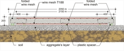
For ramp widths reaching up to 2.5 m and since there it is possible to cast and vibrate concrete from both sides of the ramp, rebar chairs can be replaced by open-form folded wire meshes (hairpins) or by closed form folded wire meshes which at the same time will provide efficient co-hesion of the ramp’s edges.
 A combination of reinforcement, support and lap-splicing of an industrial wire fabric reinforcement Τ188 (Ø 6/150 with dimensions 2.15x5.0 m)
 A combination of reinforcement, support and lap-splicing of an industrial wire fabric reinforcement Τ188 (Ø 6/150 with dimensions 2.15x5.0 m)
- In case of an extremely well-formed substrate, it is allowed to use only a single wire mesh which will be placed for example at the 2/3 of the ramp’s thickness.
- In a ramp, stresses can be created in both directions; therefore, always assuming the same behaviour, the placed wire mesh is usually of a square shape. The wire meshes used for the ramp’s reinforcement must be normally lap-spliced (in usual cases a length of 2 up to 3 openings is enough).
- Heavy-duty ramps require edge reinforcement as well. That reinforcement can be also used as rebar chairs.
- The edge behavior does not appear only to the ramps’ edges but also to the areas around joints. The joint edges are treated by the same way as the side edges. It is useful to place the joints in the shortest possible distances e.g. every 15 meters.
Extended building slabs on ground, are mainly floors constructed upon the upper basement af-ter the foundation’s embankment .
The slab on ground is an element analogous to the ramp on ground and their behavior is almost alike. The reinforcement is implemented in the same way. However, it involves an additional difficulty that arises due to the extended slab’s surface which in the case of a double wire mesh creates problems in both the reinforcement implementation and the concrete casting.
1. The problem of securing the double wire mesh’s proper position at the upper and lower parts of the slabs is not that intense in the superstructure because: firstly, there are the beams that separate and support the slabs’ reinforcement and secondly, the reinforce-ment of the slabs is strong and therefore, carries effectively not only its self weight but also the loads applied by the movement of the personnel responsible for the steel fixing and the concrete casting.
2. The solution to this problem is (a) a well-formed surface with fine aggregates properly compacted, or an additionally casted thin layer of concrete (30 to 50 mm) and (b) usage of narrow spaced rebar chairs (with practices similar to those mentioned in paragraph 2.6.1)
3. A larger live load, applied upon the slab, requires the use of a stronger wire mesh.
4. Generally, the standardized wire mesh with square openings like Τ131(#Ø5/150), Τ196(#Ø5/100) and T188(#Ø6/150) of steel class B500A [table 2], presents a satisfac-tory behavior under the common loads applied on basements’ slabs.