|
« Diaphragmatic function
Deformations-Stresses »
|
There are several more or less accurate methods for the dynamic analysis of a space frame subjected to seismic action. However, all of them are approximate, as expected for such a complicated combination of geological and structural objects. They are described in detail by Avramidis at al. (2011). Considering the contemporary technology of high speed computers, a very good choice would be the response spectrum method which should be combined with the Complete Quadratic Combination (CQC) method to obtain the envelope of the stress resultants. The disadvantage of the CQC method is that it results only to positive values, which makes the determination of the most unfavourable combinations of biaxial bending difficult. This is, however, handled with various approximate techniques. Τhe related software, that accompanies this book, uses two such similar methods. The first one applies CQC to all stress resultants and displacements. All stress resultants are examined for both positive and negative signs (32 combinations, see §6.5), thus the results are satisfactory. There is also another simple method overcoming the sign related problem providing reasonable results according to classical static analysis (see §6.3.2). The steps of the method are: - The calculation of seismic accelerations ai,j (j=x,y,z), at any point i along X, Y, Z directions, using CQC. The calculation takes into account the soil parameters of the earthquake, the seismic ground acceleration, the masses participating at the time of the earthquake at the point i and the available ductility of the building. The sign of accelerations ai,j derives from the dominant mode (i.e. the mode with the highest modal participation factor).
- The calculation of seismic forces Hi,j=ai,j·Mi at any point i, as the algebraic product of the seismic acceleration and the mass at this point.
- The calculation of seismic stresses in X, Y, Z direction for every seismic combination (e.g. earthquake in Y + 30%, earthquake in X + 20%, earthquake in Z), based on the seismic forces.
- In case the seismic combination includes accidental eccentricities, each mass M of a node i is placed at the position of the node i offset by the signed value (+ or -) of the eccentricities. In this way, all cases of nodes are resolved, whether they belong to the diaphragm or not. If all nodes of a floor belong to the diaphragm, the resultant loading is equivalent to the one that would result if the total mass of the floor was offsetted from the center of mass by the amount of the accidental eccentricities.
- Τhe stress resultants of each combination are signed according to the classical static analysis.
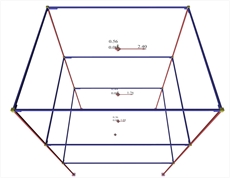
.jpg?bhow=0&w=500&h=500&Str=0) Figure 3.2-1: Earthquake in x: Calculation of seismic forces using CQC for all mode shapes
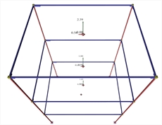
Figure 3.2-1: Earthquake in x: Calculation of seismic forces using CQC for all mode shapes Figure 3.2-1: Earthquake in x: Calculation of seismic forces using CQC for all mode shapes  Figure 3.2-2 Seismic accelerations for seismic action in X
 Figure 3.2-2 Seismic accelerations for seismic action in X |  Figure 3.2-3 Seismic accelerations for seismic action in Y
 Figure 3.2-3 Seismic accelerations for seismic action in Y |
Τhe advantage of the second method is that it provides orders of magnitudes in terms of classical static analysis understandable to the engineer. For instance, the seismic accelerations at the diaphragmatic floors of common buildings should follow an almost triangular distribution with zero value at the base of the building and the design acceleration ao at its centroid. Τhis triangle is indicated by the red dashed line at the Interface of the related software so that the engineer is able to check the order of magnitude of the distribution of the seismic accelerations. Furthermore, using this method there is no need for additional dynamic response spectrum analysis. -
The main comparison is performed on seismic accelerations. This is based on the fact that seismic forces provide the same fast visual outcome with respect to their vertical distribution, provided that all floor masses are identical. -
When the principle system is inclined, for earthquake in x direction only, the seismic accelerations are developed in both x, y directions. Τhe same stands for earthquake in y direction only. -
The earthquake in x direction generates components in x direction only when the structure is symmetrical, otherwise it generates components in both directions.
|
| Earthquake in Y Direction | | | | | | |
|
|
|
| Figure 3.2-4: Ten-storey building
of a non-symmetrical mixed
system (project B_547-3b) | Figure 3.2-5: Distribution of Seismic Accelerations
-Forces-Shears |
|
« Diaphragmatic function
Deformations-Stresses »
|

|