Shear forces and support reaction forces A slab supported on all four edges with an aspect ratio of longer to shorter theoretical span less than ≤2.00, is considered to be two-way. Static analysis of two-way slabs, subjected to uniform load, is performed using tables, which give the fundamental support moments, span moments and shear forces. In these tables, each slab is characterized by a number from 1 to 6, depending on the type of support, as illustrated in the following figure:  Figure 4.6
 Figure 4.6 The floor diaphragm, as a rule, consists of many connected slabs affecting each other. The accurate calculation of these influences is performed only by means of two dimensional finite elements. In usual cases, shear and reaction forces are not affected by adjacent slabs. An additional reason for considering slabs isolated, is to use simplified methods for the calculation. Distribution of load is considered as triangular or trapezoidal. Heights of triangles/trapezoids determine the maximum values of load transferred to the corresponding points of the peripheral support. These maximum loads are the maximum shear forces Vi,j of the slab, while equivalent loads p i,j represent the equivalent uniform reactions. The distribution of reaction forces may be calculated according to the following simplified rule: 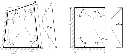 Figure 4.6.1.1-1
 Figure 4.6.1.1-1 -
At the intersection of two similar edges (both fixed and simply supported) load is distributed with sharing angle φ/2 (45ο for rectangular slab). -
· At the intersection of two dissimilar edges (one fixed and the other simply supported), load is distributed with sharing angle 2φ/3 towards the fixed edge (60º for rectangular slab) and φ/3 towards the simply supported edge (30º for rectangular slab).
-
In the example presented in the previous figure, the equivalent rectangular slab is indicated by a red dashed line. Dimensions lx', l y' are determined bu considering equal area and moments of inertia. -
The above rule for the load distribution is also valid for slabs with more than four edges. -
The load distribution rule adopted approximates the accurate one according to elasticity theory. In practice, trapezoidal loading represented by equivalent rectangular, as shown in the following figures. -
Supports which are not taken into account in the calculation of a slab, should participate in the load distribution. -
The same approach may be applied to slabs supported on two or three edges.
The values of coefficients of shear forces Vi,j and equivalent uniform reactions pi,j are given in the six tables b5.1 to b5.6 cite in the end of the book. 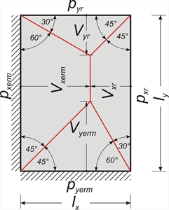 Figure 4.6.1.1-2
 Figure 4.6.1.1-2 In each of six support cases two triangles and trapezoids are formed in directions x, y or conversely (depending on the side ratio). Next, the general case of slabs is considered for two aspect ratios where S≥0 (as shown in the two following figures). Tables b5 have been composed according to the resulting equations.
General simplified calculation of shear forces and reaction forces 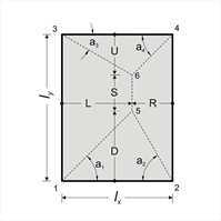 Figure 4.6.1.1-3
 Figure 4.6.1.1-3
VL=L·p=ρL·p·lx, VR=R·p=ρR·p·lx, VD=D·p=ρD·p·lx, VU=U·p=ρU·p·lx pL=(A1,3,6,5·p)/ly=υL·p·lx pR=(A2,4,6,5·p)/ly=υR·p·lx, pD=(A1,2,5·p)/lx=υD·p·lx | 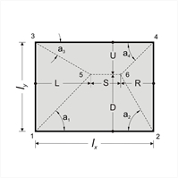 Figure 4.6.1.1-4
 Figure 4.6.1.1-4
VL=L·p=ρL·p·lx, VR=R·p=ρR·p·lx, VD=D·p=ρD·p·lx, VU=U·p=ρU·p·lx pR=(A2,4,6·p)/ly=υR·p·lx, pD=(A1,2,6,5·p)/lx=υD·p·lx pU=(A3,4,6,5)·p/lx=υU·p·lx | D=[1/(cota1+cota2)]·lx=ρD·lx , where ρD=1/(cota1+cota2) U=[1//(cota3+cota4)]·lx=ρU·lx , where ρU=1/(cota3+cota4) L=[cota1/(cota1+cota2)]·lx=ρL·lx , where ρL=cota1/(cota1+cota2) R=[cota2/(cota1+cota2)]·lx=ρR·lx , where ρR=cota2/(cota1+cota2) pL=A1,3,6,5/ly=0.50·(ly+S)·L/(ε·lx)=0.50·(2ε-ρD-ρU)·ρL·lx·lx/(ε·lx)=υL·p·lx , where υL=[0.50·(2ε-ρD-ρU)·ρL]/ε pR=A2,4,6,5/ly=0.50·(ly+S)·R/(ε·lx)=0.50·(2ε-ρD-ρU)·ρR·lx·lx/(ε·lx)= =υR·p·lx , where υR=[0.50·(2ε-ρD-ρU)·ρR]/ε pD=(A1,2,5·p)/lx=0.50·lx·D/lx=0.50·ρD·lx , whereυD=0.50·ρD pU=(A3,4,6·p)/lx=0.50·lx·U/lx=0.50·ρU·lx , where<υU=0.50·ρU Verification: (α) S≥0, (b) L+R=lx, (c) υL+υR+(υD+υU)/ε=1.0 Example: slab type 4, lx=4.0 m, ly=6.0 m, p=15.0 kN/m2 ε=ly/lx=6.0/4.0=1.5. For slab type 4 a1=45°, a2=60°, a3=30°, a4=45°, thus ρyerm=ρD=0.634, ρyr=ρU=0.366, ρxerm=ρL=0.634, ρxr=ρR=0.366 S=(1.5-0.634-0.366)·lx=0.50·lx υxerm=υL=[0.50x(2x1.5-0.634-0.366) x0.634]/1.5=0.423 υxr=υR=[0.50x(2x1.5-0.634-0.366) x0.366]/1.5=0.244 υyerm=υD=0.50·ρD=0.50x0.634=0.317 υyr=υU=0.50·ρU=0.50x0.366=0.183 Vxerm=ρxerm·p·lx=0.634x15.0x4.0=38.04 kN/m Vxr= ρxr·p·lx=0.366x15.0x4.0=21.96 kN/m Vyerm= ρyerm·p·lx=0.634x15.0x4.0=38.04 kN/m Vyr= ρyr·p·lx=0.366x15.0x4.0=21.96 kN/m pxerm=υxerm·p·lx=0.423x15.0x4.0=25.38 kN/m pxr= υxr·p·lx=0.244x15.0x4.0=14.64 kN/m pyerm= υyerm·p·lx=0.317x15.0x4.0=19.02 kN/m pyr= υyr·p·lx=0.183x15.0x4.0=10.98 kN/m | L=[1/(tana1+tana3)]·ly=ρL·lx, where ρL=ε/(tana1+tana3) R=[1/(tana2+tana4)]·ly=ρR·lx, where ρR=ε/(tana2+tana4) D=[tana1/(tana1+tana3)]·ly=ρD·lx, where ρD=(ε·tana1)/(tana1+tana3) U=[tana2/(tana1+tana3)]·ly=ρU·lx, where ρU=(ε·tana3)/(tana1+tana3) pL=(A1,3,5·p)/ly=0.50·ly·L/ly=0.50·ρL·lx, where υL=0.50·ρL pR=(A2,4,6·p)/lx=0.50·ly·R/ly=0.50·ρU·lx, where υR=0.50·ρR pD=A1,2,6,5/lx=0.50·(lx+S)·D/lx=0.50 · (2-ρL-ρR)·ρD·lx·lx/lx=υD·p·lx, where υD=0.50·(2-ρL-ρR)·ρD pU=A3,4,6,5/lx=0.50·(lx+S)·U/lx=0.50 · (2-ρL-ρR)·ρU·lx·lx/lx=υU·p·lx, where υU=0.50·(2-ρL-ρR)·ρU Verification: (a) S≥0, (b) D+U=ε·lx, (c) υL+υR+(υD+υU)/ε=1.0 Example: slab type 4, lx=6.0 m, ly=4.0 m, p=15.0 kN/m2 ε=ly/lx=4.0/6.0=2/3. For slab type 4 a1=45°, a2=60°, a3=30°, a4=45°, thus ρxerm=ρL=0.423, ρxr=ρR=0.244, ρyerm=ρD=0.423, ρyr=ρU=0.244, S=(1-0.423-0.244)·lx=0.333·lx υxerm=υL=0.50·ρL=0.50x0.423=0.212 υxr=υR=0.50·ρR=0.50x0.244=0.122 υyerm=υD=0.50x(2-0.423-0.244)x0.423=0.282 υyr=υU=0.50x(2-0.423-0.244)x0.244=0.163 Vxerm=ρxerm·p·lx=0.423x15.0x6.0=38.07 kN/m Vxr=ρxr·p·lx=0.244x15.0x6.0=21.96 kN/m Vyerm= ρyerm·p·lx=0.423x15.0x6.0=38.07 kN/m Vyr= ρyr·p·lx=0.244x15.0x6.0=21.96 kN/m pxerm=υxerm·p·lx=0.212x15.0x6.0=19.08 kN/m pxr= υxr·p·lx=0.122x15.0x6.0=10.98 pyerm=υyerm·p·lx=0.282x15.0x6.0=25.38 kN/m pyr= υyr·p·lx=0.163x15.0x6.0=14.67 kN/m |
Czerny's elasticity method 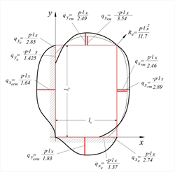 Figure 4.6.1.2-1: Shear force diagram by Czerny for side
ratio 1.50 Figure 4.6.1.2-1: Shear force diagram by Czerny for side
ratio 1.50 According to the theory of elasticity, the distribution of shear forces along the length of the four edges of a slab, results from the shear forces along its perimeter as described by equations. The most unfavourable shear forces along the sides of a slab (as well as the most unfavourable bending moments) are tabulated in the tables of the book entitled "Applications of Reinforced Concrete" (p46-51 for two-way slabs, p52-59 three- or two-side-supported slabs) of series of books by Apostolos Konstantinidis published in1994. 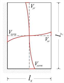 Figure 4.6.1.2-2
 Figure 4.6.1.2-2 Depending on the ε = lx / ly (where lx is the shortest dimension) and the type of support, shear forces at the edges are equal to:
-
The simplified method produces more unfavourable shear forces than the previously reported tables. -
Both the elasticity equations and the corresponding tables, refer to orthogonal slabs or symmetric combinations of them. The general solution taking into account various shapes and arbitrary arrangement of slabs is obtained accurately only by means of the finite element method.
|