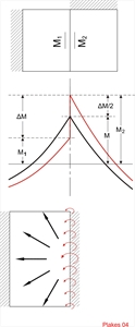
 Figure 4.3.1
 Figure 4.3.1 A building usually comprises several, generally non-standard, types of slabs (one-way, two-way etc.). In this case, each slab is analysed separately by using tables. The moments M at the edge (border) of two slabs could be taken as the average of moments M1 (left slab moment) και M2 (right slab moment).
The difference ΔΜ=M2-M1 is redistributed in all directions of slabs, affecting less the other support moments and even lesser the span moments. Special types of plates (inclined, of non-constant thickness etc.) could be solved as equivalent rectangular slabs of constant thickness.
Application width of concentrated load on slab 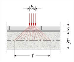 Figure 4.3.2
 Figure 4.3.2 The application width t of concentrated load P onto the middle level of the slab is expressed as: t = b0 + 2·(s+hs/2) = b0 + 2·s + hs , where s is the covering thickness. Thickness s should not be taken into consideration, when the concentrated load is applied directly onto the concrete's surface, e.g. in the case of brick masonry.
Distribution width of concentrated load 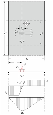 Figure 4.3.3-1: One-way slab bearing
concentrated load Figure 4.3.3-1: One-way slab bearing
concentrated load In case of concentrated, linear or uniformly distributed load applied on one-way slab, unless more accurate analysis is performed, the calculated distribution width bm is defined transversely to the direction of main reinforcement. Symbols used: bm,f is the distribution width of span moment, bm,s is the distribution width of the support bending moment (provided fixed support exists) and b m,v (bm,vL, bm,vR) is the distribution width of shear force (at left and right support). These widths, generally, differ. Each stress resultant aw at each position x of one-way slab LR, due to uniform load pd=γg·g+γq·q, remains constant along the entire lengthly with units of moment or shear per m in direction y. Concentrated load P=γg·G+γq·Q causes additional stress resultant AP (in units of moment or shear) corresponding to the distribution width BM, thus is equal to aP=AP/bm per m in direction y . According to superposition principle, the total stress resultant applied on bm wide strip is equal to atot=aw+aP, while on the rest width ly is equal to aw. The distribution width of the concentrated load is a function of the support types of the slab (fix, simple, free) and the distance x between the centre of mass and the supports. The following table gives the distribution width of partial uniform load for every type of support.
Distribution width of partial uniform load | |
| b m , f = ty + 2.5·x·(1-x/l) t x,max = l, t y,max = 0.8l | t x,max = l, t y,max = 0.8l b m , vR = t y + 0.5·(l-x) t x,max = l, t y,max = 0.8l | | | bm,f=0.37+2.5x1.5x(1-0.375)=2.71 m | bm,vL=0.37+0.5x1.5=1.12 m bm,vR=0.37+0.5x2.5=1.62 m | | | bm,f=0.37+2.5x2.0x(1-0.5)=2.87 m | bm,vL=0.37+0.5x2.0=1.37 m bm,vR=0.37+0.5x2.0=1.37 m | Simple with
one end
fixed |
| b m , f = t y + 1.5·x·(1-x/l) t x,max = l, t y,max = 0.8l b m ,s = t y + 0.5 · x·(2-x/l) t x,max = l, t y,max = 0.8l | t x,max = 0.2l, t y,max = 0.4l t x,max = 0.2l, t y,max = 0.4l | | | bm,f=0.37+1.5x1.5x(1-0.375)=1.78 m bm,s=0.37+0.5x1.5x(2-0.375)=1.59 m | bm,vL=0.37+0.3x1.5=0.82 m bm,vR=0.37+0.4x2.5=1.37 m | | | bm,f=0.37+1.5x2.0x(1-0.5)=1.87 m bm,s=0.37+0.5x2.0x(2-0.5)=1.87 m | bm,vL=0.37+0.3x2.0=0.97 m bm,vR=0.37+0.4x2.0=1.17 m | | |
| b m , f = t y + x·(1-x/l) t x,max = l, t y,max = 0.4l b m ,sL = t y + 0.5·x·(2-x/l) b m ,sR = t y + 0.5·(l-x)·(1+x/l) t x,max = l, t y,max = 0.4l | t x,max = 0.2l, t y,max = 0.4l b m ,vR = t y + 0.3·(l-x) t x,max = 0.2l, t y,max = 0.4l | | | bm,f=0.37+1.5x(1-0.375)=1.31 m bm,sL=0.37+0.5x1.5x(2-0.375)=1.59 m bm,sR=0.37+0.5x2.5x(1+0.375)=2.09 m | bm,vL=0.37+0.3x1.5=0.82 m bm,vR=0.37+0.3x(4.0-1.5)=1.12 m | | | bm,f=0.37+2.0x(1-0.5)=1.37 m bm,s=0.37+0.5x2.0x(2-0.5)=1.87 m bm,sR=0.37+0.5x2.0x(1+0.5)=1.87 m | bm,vL=0.37+0.3x2.0=0.97 m bm,vR=0.37+0.3x(4.0-2.0)=0.97 m | | |
| t x,max = l, t y,max = 0.8l | t x,max = 0.2l, t y,max = 0.4l | | | | | | | | |
Examples 1 and 2 are presented below. Example 1 (slab at the start of paragraph 3.3.1) 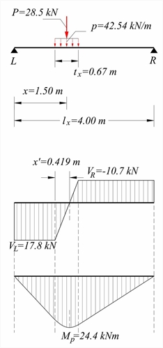 Figure 4.3.3-2
 Figure 4.3.3-2 Dimensions of slab lx=4.00 m, ly=5.00 m, width hs=170 mm. Subjected to covering load ge=1.0 kN/m2, live load q=5.0 kN/m2 and concentrated P (dead G=10.0 kN and live Q=10.0 kN), applied directly (s=0) onto the slab, with dimensions b ox=0.50 m, boy=0.20 m and distance of center of mass from left support x=1.50 m. L, R are pin supports. Calculate bending moment and shear force diagrams. The analysis with uniform loads is the same as in the example of §3.3.2 (vw=29.18 kN/m, mw=29.18 kNm/m). This design load is uniform along the entire length ly of the slab. The application width of the design concentrated load P is P=1.35·G+1.50·Q=1.35x10.0+1.50x10.0=28.5 kN tx=box+hs=0.50+0.17=0.67 m ty=boy+hs=0.20+0.17=0.37 m The equivalent linear distributed load p in txis p=P/tx=28.5kN/0.67m=42.5 kN/m The support shear forces are VL=Vx,L=p·tx·(lx-x)/lx=42.54x0.67x2.5/4.0=17.8 kN VR=Vx,R=Vx,L-p·tx=17.81-42.54x0.67=-10.7 kN The zero shear force point is located at x'=VL/p=17.81kN/(42.54kN/m)=0.419 m The maximum moment is (see § 3.3.3, sub note 10) The load widths are (previous table): tx,max=lx=4.0 m (>tx=0.67 m) και ty,max=0.8·lx=0.8x4.0=3.20 m (>ty =0.37 m) The additional design moment at a strip of width bm,f=2.71 m is equal to mP=MP/bm,f=24.48kNm/2.71m=9.03 kNm/m while the total design moment is equal to mtot=mw+mP=29.18+9.03=38.21 kNm/m. The additional design shear force at a strip of width bm,vL=1.12 m is equal to vP=VL/bm,vL=17.81kN/1.12m=15.9 kN/m while the total design shear force is equal to vtot=vw+vP=29.2+15.9=45.1 kN/m. In the previous slab, additional constant load g=8.0 kN/m is applied due to masonry from L to R (total load G=8.0kN/m·4.00m=32.0 kN) on width boy=0.20 m. Calculate bending moment and shear force diagrams. The analysis with uniform loads is the same as the previous example. The load strip dimensions are box=4.00 m and boy=0.20 m. 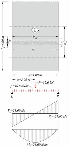 Figure 4.3.3-3
 Figure 4.3.3-3 The application width of the design concentrated load p is: p=γg·g=1.35x8.0kN/m=10.8 kN/m tx=min(box+hs, lx)=min(4.00+0.17, 4.00)=4.00 m ty=boy+hs=0.20+0.17=0.37 m The support shear forces are VL=VR=p·lx/2=10.8x4.00/2=21.6 kN Mp=p·l2x/8=10.8x4.002/8=21.6 kNm. The distribution load widths are (previous table) ty,max=0.8·lx=0.8x4.00=3.20 m(>ty=0.37 m) bm,f=ty+2.5·x·(1-x/l)=0.37+2.5x2.00x(1-0.50) bm,vL=bm,vR=ty+0.5·x=0.37+0.5x2.00=1.37 m The additional design moment at a strip of width bm,f=2.87 m is equal to mp=Mp/bm,f=21.60kNm/2.87m=7.5 kNm/m while the total design moment is equal to mtot=mw+mP=29.2+7.5=36.7 kNm/m. The additional design shear force at a strip of width bm,vL=1.37 m is equal to vP=VL/bm,v=21.6kN/1.37m=15.8 kN/m while the total design shear force is equal to vtot=vw+vP=29.2+15.8= =45.0 kN/m. -
The slab of the two previous examples is designed for bending with moment mw=29.2 kNm/m (strip width 1.00 m). The respective reinforcement a s,w (mm2/m) is placed uniformly along full length ly=6.00 m. -
Slab strip bm,f should be designed for bending using strip width 1.00 m and moment mtot, resulting to reinforcement as,tot (mm2/m). The additional required reinforcement for strip bm,f is equal to as=as,tot-as,w (mm2/m) and As=as·bm,f (mm2), is distributed on a strip of width b zwith ty≤ bz ≤bm,f, symmetrically with respect to the load. -
In addition to longitudinal reinforcement, transverse reinforcement is also required both in upper and lower fiber of the strip, equal to at least 60% of as having length bm,f + anchorage length. If a strip is selected, e.g. of width bz=0.40 m, it can form a hidden beam shape, contributing to the support of upper transverse reinforcement (see volume C'). This means that the distribution area is reinforced as flange of web width bz=0.40 m and slab width bm,f. -
The slabs of the previous examples are designed for total shear v=45. 1 kN for strip width 1.00 m.
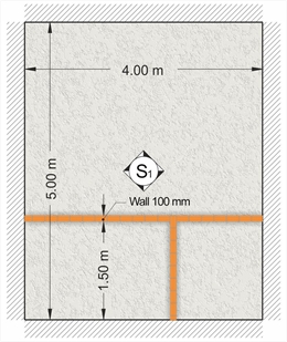 Figure 4.3.3-4
 Figure 4.3.3-4 In the case of two-way slab, concentrated or linear loads are distributed all over the slab as equivalent uniform load. This load is added to other uniform loads of the slab. Example : The equivalent uniform linear load of masonries of the figure (e.g. the weight of masonry minus the weight of the door), along directions of 4.00 and 1.50 m are equal to 5.0 kN/m and 6.0 kN/m, respectively. Calculate the equivalent uniform load of the masonries distributed in the entire surface of the slab. 4.00m·5.0kN/m+1.50m·6.0kN/m=29.0 kN Equivalent uniform load of masonry: 29.0kN/(4.00m·5.00m)=1.45 kN/m2
|