|
« FORMWORK OF THE FOUNDATION and the basement floor (Drawing C.20)
FORMWORK of the GROUND FLOOR’S ceiling (Drawing C.40) »
|
FORMWORK of the BASEMENT’S ceiling (Drawing C.30) The drawing of the basement ceiling’s formwork includes the formwork plan view and a charac-teristic elevation, both in 1:50 scale. Moreover, it shows the details of the two staircases in 1:20 scale and the details of the peripheral shear walls’ waterproofing in scale 1:10. The axes and the fixed points of the columns must be re-defined in the basement level. Two heights are mentioned upon the formwork drawing, the first regards the height of the slab’s covering and the second refers to the height of the concrete’s upper surface. Although many of these altitudes appear to be unnecessary they are written in order to avoid confusion during the formworks’ implementation. Normally, the channels required for the positioning of the installations, must be clearly indicated upon a special drawing however, if they are not extensive and complex they can be presented only upon the carpenter’s drawing. In case a pipe has to pass through the wall of a strip foun-dation, the designer engineer must be notified.  Detail of the drawing C.30
 Detail of the drawing C.30  Detail of the drawing C.30
Detail of the drawing C.30
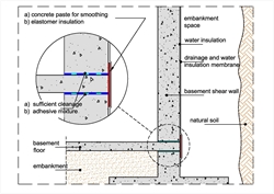
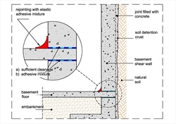
The detail that regards the proper waterproofing of the two joints formed at the base of the pe-ripheral shear walls where the layers of the final three concrete castings meet, is quite impor-tant. When it is possible to work at the outer surfaces, the solution is shown at the first figure while when there is no such possibility, we are limited to the internal sealing. It is noted again that the solutions mentioned in this paragraph constitute some of the numerous, analogous so-lutions.
|
« FORMWORK OF THE FOUNDATION and the basement floor (Drawing C.20)
FORMWORK of the GROUND FLOOR’S ceiling (Drawing C.40) »
|

|