Bending moments in continuous two-way slabs
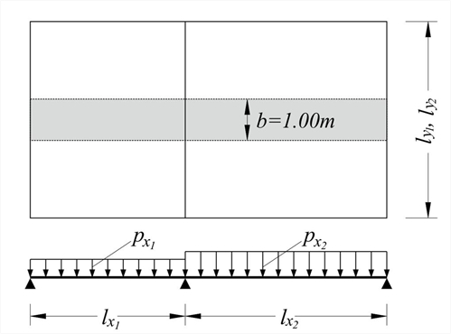
 Figure 4.6.3.1-1: Strips (zones) of 1.00 m width are considered along the directions of continuity
 Figure 4.6.3.1-1: Strips (zones) of 1.00 m width are considered along the directions of continuity
Strips are solved as continuous one-way slabs, with loads pxi and pyi applied on spans lxi and lyirespectively, using one of the known methods.
Stiffness coefficients are determined considering each strip as bar fixed either at one or both ends.
The errors associated with the calculations of stiffness by this method could be very significant, due to considering the strips as independent bars. In reality, the stiffness of slab depends on both directions.
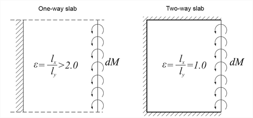
 Figure 4.6.3.1-2: One-way and Two-way slab
 Figure 4.6.3.1-2: One-way and Two-way slab
Even greater error occurs in the calculation of transfer coefficients of support moments, as well as in the calculation of span moments, due to rotation of the support (or equivalently, due to external moment imposed on the support).
These differences are shown in the next example.
 Figure 4.6.3.1-4: Stiffness index K = I / (Ic Ix) (one way slab) and K = 1.875 I / (Ic Ix) (two way slab)
 Figure 4.6.3.1-4: Stiffness index K = I / (Ic Ix) (one way slab) and K = 1.875 I / (Ic Ix) (two way slab)
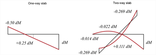
 Figure 4.6.3.1-6: Half of the transfer moment dM on the support of a one-way slab is shifted to the opposite support(left diagram).The same transfer moment dM on the support of a two-way slab is “diffused” all over its surface (right diagram)
 Figure 4.6.3.1-6: Half of the transfer moment dM on the support of a one-way slab is shifted to the opposite support(left diagram).The same transfer moment dM on the support of a two-way slab is “diffused” all over its surface (right diagram)
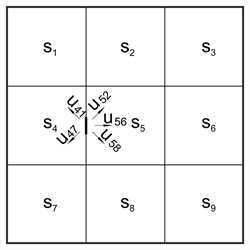
 Figure 4.6.3.2
 Figure 4.6.3.2
Stiffness coefficients and transfer indices of each slab depend on its type of support and its aspect ratio. These data are provided by tables in several books, e.g. by Hahn.
All supports are considered fixed when principal moments are calculated.
One support is freed, e.g. 45 of the figure, and distribution takes place on all directions (i.e. CROSS method on plane).
This procedure is repeated until moments balance.
Such a solution is, certainly, complex and laborious, but it is applicable in case of large spans with significant differences in dimensions and thicknesses.
Practically accurate method
In usual cases of slabs with almost the same thickness (even for large or uneven spans), support moments are calculated with reasonable accuracy according to the expression: