Behavior and reinforcement of beams and columns
FRAMES WHERE NO SEISMIC DESIGN IS REQUIRED
The following frame is composed by two columns and one beam and it bears only gravity loads i.e. no seismic loading is applied.
The following figure shows the concrete deformations and cracks. They are presented in a very large scale so as to thoroughly comprehend the way the members behave. In reality they are so small that they are not visible to the human eye.
The tensile stresses applied to some areas of concrete cause the formation of cracks; therefore in those areas the necessary reinforcement is placed. When the cracks are perpendicular to the axis of the member, longitudinal reinforcement is placed i.e. rebars that prevent the expansion of the hairline cracking. When the cracks are diagonal, transverse reinforcement i.e. stirrups is placed to control them
In the case where the frame is subjected to gravity loads only and seismic forces are not sup-posed to be applied to it, the diagonal cracking could be controlled with the use of diagonal rein-forcement.
FRAMES WHERE SEISMIC DESIGN IS REQUIRED
The following frame is exactly the same with the frame mentioned above. Both frames will be-have in exactly the same way through their lifetime except in those few seconds during an earthquake.
An earthquake ground motion causes horizontal displacements that in their turn cause horizon-tal inertia forces, forces generated by the sudden change in the kinetic state of the body.
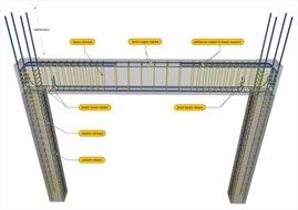 Two- column earthquake resistant frame "project: frame1"
 Two- column earthquake resistant frame "project: frame1"
During the seismic action the applied horizontal forces constantly shift direction. This results in a continuous change in the frame’s behavior, consequently the tensile stresses and thus the in-clined crackings appear in different positions and directions. This position- direction alteration is the reason why earthquake design and reinforcement detailing are so critical in areas with high seismic activity.
Fundamental rules in the reinforcement of antiseismic structural systems
The following needs – rules regarding the proper placement of reinforcement, derive from the behavior of structures:
(a) Rebars must be symmetrically placed around the perimeter of the cross section since the tensile forces and therefore the inclined cracking constantly change direction.
(b) There must be enough, high strength and properly anchored stirrups. This reinforcement protects the member from the large diagonal cracks of alternating direction, caused by the diagonal stressing or otherwise called shear.
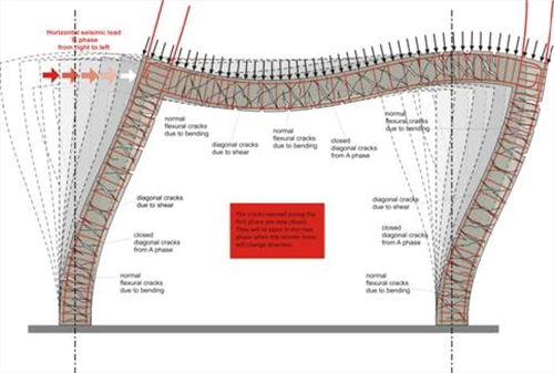 Behavior of a two–column frame during an earthquake.
 Behavior of a two–column frame during an earthquake.
(a) Rebars placed in the beams lower part must be as well anchored as those placed in the upper part. This happens because tension and therefore the resulting transverse crack-ing, continuously change place during a seismic action and as a consequence in critical earthquakes, tensile stresses appear to the lower fibers of the supports.
(b) There must be enough, high strength and properly anchored stirrups because the high intensity of the diagonal stresses and thus the large inclined diagonal cracking, shift di-rection during an earthquake.
No matter how “well designed” a structure is, either because of exceeded design seismic forces or because of local conditions during the construction, one or possibly more structural members will exceed their design strength. In this case we desire to have two defense mechanisms:
1st defense mechanism: in case of an earthquake greater than the design earthquake we don’t want failure (fracture) of any member even if it remains permanently deformed, this means that we need ductile structural members.
2nd defense mechanism: in the case of an extremely intense earthquake, where failure of some members is unavoidable, the elements that must not exceed their strength are columns; this means that the columns must have sufficient capacity-overstrength.
In the second defense mechanism all failures must be flexural because of their ductile na-ture as opposed to shear failures that have a brittle behavior (i.e. sudden fracture).
By designing the structure to withstand a major seismic incident, something achieved by the use of a high seismic factor, we avoid extensive failures. By providing ductility and capacity-overstrength to the elements we design against local failures. Local failure may happen for vari-ous reasons and if it occurs it may lead to the progressive failure of the structure.
The need for ductility in structural elements
In both columns and beams supports , it is required to place a substantial amount of stirrups not only to bear the diagonal tension but also to ensure a high level of ductility which is crucial in the case of strong earthquakes.
Ductility is the ability of a reinforced concrete member to sustain deformation after the loss of its strength, without fracture.
When design seismic actions are exceeded, only one element, the most vulnerable, will over-come its strength capacity. If that element is ductile, it will continue to bear its loading and will give the second most vulnerable element the possibility to contribute its strength. If that second element is ductile too, it will make the third most vulnerable element to contribute its strength and that way all the elements will successively supply their strength.
If all members of the structural system have enough ductility the structure’s strength ca-pacity will depend on the strength capacity of all the structural members, otherwise it will depend on the strength capacity of the most vulnerable structural member.
Ductility i.e. the element’s deformation capability beyond its yielding point regards flexure and requires strength in shear. This is the reason why shear design is based on the elements ca-pacity-overstrength so as to avoid potential shear failure.
Columns and beams basically fail in the joint area i.e. the area where the beam intersects with the column. Therefore columns and beams must be enough ductile in the joint area. If pounding between a column and a staircase or masonry infill is probable then the need for adequate duc-tility extents to the whole length of the column.
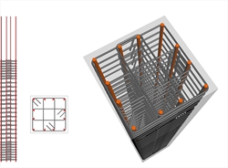 Column with cross-section 500x500 and three stirrups on every layer, required by the Seismic Regulation for ductility.
 Column with cross-section 500x500 and three stirrups on every layer, required by the Seismic Regulation for ductility.
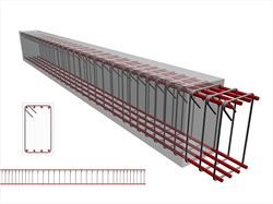 Beam with ductility requirements
 Beam with ductility requirements
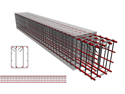 Beam with high ductility requirement
 Beam with high ductility requirement
The need for column’s capacity-overstrength
Capacity design ensures that the columns will have greater capacity than the adjacent beams therefore no matter how intense the seismic action will be, beam failure will precede the failure of columns. Failing beams will absorb part of the released seismic energy thus altering the structure’s natural (fundamental) frequency and avoiding resonance. Generally, failure of one or more beams does not induce progressive failing, hence even in an extremely strong seismic event, the structure will not collapse and will retain a minimum serviceability level allowing its evacuation and most of the times its rehabilitation.