Centre of stiffness and elastic displacements of the diaphragm The current paragraph examines the special case of orthogonal columns in parallel arrangement. The general case is examined in Appendix C. .jpg?bhow=0&w=500&h=500&Str=0) Figure 5.4.3.1-1: Simple one-storey structure comprising four columns, whose tops are connected by a rigid slab-diaphragm.
Figure 5.4.3.1-1: Simple one-storey structure comprising four columns, whose tops are connected by a rigid slab-diaphragm. Figure 5.4.3.1-1: Simple one-storey structure comprising four columns, whose tops are connected by a rigid slab-diaphragm. .jpg?bhow=0&w=500&h=500&Str=0) Figure 5.4.3.1-2: Parallel translation of the diaphragm in both directions and rotation ,due to a force H applied to the centre of mass CM.(Χ0Υ initial coordinate system, xCTy main coordinate system)
Figure 5.4.3.1-2: Parallel translation of the diaphragm in both directions and rotation ,due to a force H applied to the centre of mass CM.(Χ0Υ initial coordinate system, xCTy main coordinate system) Figure 5.4.3.1-2: Parallel translation of the diaphragm in both directions and rotation ,due to a force H applied to the centre of mass CM.(Χ0Υ initial coordinate system, xCTy main coordinate system) The diaphragmatic behaviour may be considered as a superposition of three cases: (a) parallel translation of the diaphragm along the X direction due to horizontal force component HX, (b) parallel translation of the diaphragm along the Y direction due to horizontal force component HY, (c) rotation of the diaphragm due to moment MCT applied at the centre of stiffness CT. The horizontal seismic forces are applied at each mass point, while the resultant force is applied at the centre of mass CM. In case the direction of the force H passes through the point CT as well as CM the moment has zero value and therefore the diaphragm develops zero rotation. Translation of centre of stiffness CT along x direction 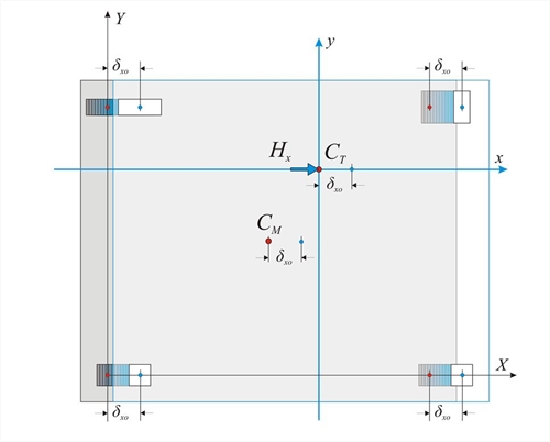 Figure 5.4.3.2: Parallel translation along the x direction due to force Hx applied at CT
 Figure 5.4.3.2: Parallel translation along the x direction due to force Hx applied at CT In case a horizontal force Hx is applied at CT in x direction, the following 2 equilibrium equations apply: - The sum of forces in x direction is equal to Hx, i.e. Hx=Σ(Vxoi ) (i).
- The sum of moments Vxoi about the point CT is equal to zero, i.e. Σ(Vxoi ·yi)=0 (ii).
Each column i carries a shear force Vxoi=δxo·Kxi. Σ (Vxoi)= Σ ( δ xo · Kxi)= δ xo · Σ (Kxi), expression (i) gives Hx=δxo·Σ(Kxi) → Hx=Kx · δ xo where Kx= Σ (Kxi). Expression (ii) gives Σ(Vxoi·[Yi-YCT])=0 → Σ(Vxoi·Yi )-Σ(Vxoi·YCT)=0 → YCT·Σ(Vxoi)= Σ(Vxoi ·YCT) → YCT= Σ ( δ xo · Kxi · Yi)/ Σ ( δ xo · Kxi) → YCT= Σ (Kxi · Yi)/ Σ (Kxi) Translation of centre of stiffness CT along y direction 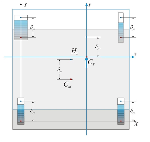 Figure 5.4.3.3: Parallel translation in y direction due to force Hy applied at CT
 Figure 5.4.3.3: Parallel translation in y direction due to force Hy applied at CT Accordingly, the corresponding expressions are derived for direction y. Hy=Ky · δ yo where Ky=Σ(Kyi) andXCT=Σ(Kyi·Xi)/Σ (Kyi) Summarising, the centre of stiffness and the lateral stiffnesses are defined by the following expressions: Centre of stiffness and lateral stiffnesses: Rotation of the diaphragm by an angle θz about CT 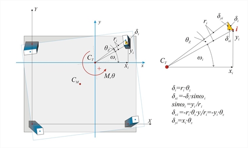 Figure 5.4.3.4: Displacements due to rotation developed from moment M applied at CT
 Figure 5.4.3.4: Displacements due to rotation developed from moment M applied at CT Principal coordinate system The displacement of the diaphragm consists essentially of a rotation θz about the CT, inducing a displacement δi at each column top i with coordinates xi,yi in respect to the coordinate system with origin the CT. If the distance between the point i and the CT is ri, the twocomponents of the (infinitesimal) deformation δi are equal to δxi=-θz·yi and δyi= θz·xi. The shear forces Vxi and Vyi in each column developed from the displacements δ xi, δyi are: Vxi=Kxi · δ xi =Kxi · (- θ z · yi)→ Vxi=-θz·Kxi·yi and Vyi=Kyi·δyi=Kyi·(θz·xi) → Vyi= θz·kyi·xi The resultant moment of all shear forces Vxi, Vyi about the centre of stiffness is equal to the external moment MCT, i.e. MCT= Σ (-Vxi · yi+Vyi · xi+Kzi) → MCT= θ z · Σ (Kxi · yi2+Kyi · xi2+Kzi) Torsional stiffness Kzi of column i Columns resist the rotation of the diaphragm by their flexural stiffness expressed in terms Kxi·yi2 , Kyi·xi2 (in N·m), and their torsional stiffness Kzi, which is measured in units of moment e.g. N ·m. The torsional stiffness of a column is given by the expression Kz=0.5E·Id/h, where 0.5Ε is the material shear modulus G, usually taken equal to 0.5 of the elasticity modulus, h is the height of the column and Id is the torsional moment of inertia of the column's cross-section, taken from the following table.
| | | |
| | |
| |
| where n is taken from the following expression | The torsional stiffness of columns Kz is very small and is usually omitted. Torsional stiffness of the floor diaphragm The quantity Κθ is the torsional stiffness of the diaphragm and is measured in N ·m. The quantities Kx=Σ(Kxi), Ky=Σ(Kyi), measured in N/m, imply the lateral stiffnesses of the diaphragm in x and y directionrespectively . Torsional stiffness K θ of diaphragm denotes the moment required to cause relative rotation of the diaphragm by one unit. Torsional stiffness ellipse, torsional radii and equivalent system Question: Create a simple idealised equivalent structural system with the same seismic behaviour as the actual structural system. Solution: Four idealised columns E1, E2 and E3, E4 are placed symmetrically with respect to the centre C T and the axes x and y, i.e. all four idealised columns have the same absolute value of coordinates x and y. Each idealised column isassumed to have stiffnesses Kx=1/4·Σ(Kxi) and Ky=1/4 ·Σ(Kyi). 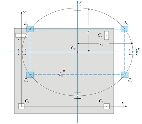 Figure 5.4.3.5-1
 Figure 5.4.3.5-1 This system satisfies the two conditions of the actual system, concerning the translations of all diaphragm columns. Stiffness by x: 4·1/4·Σ(Kxi)=Σ(Kxi) and stiffness by y: 4·(1/4)·Σ (Kyi)=Σ(Kyi) To satisfy the third condition, the torsional stiffness of the idealised system should be K θ, eq =[4 · (1/4) · Σ(Kyi)·y2+4·(1/4)·Σ(Kxi)·x2]=Σ(Kxi)·y2+Σ(Kyi)·x 2 equal to the torsional stiffness of the actual system K θ ,re = Κθ = Σ (Kxi · yi2+Kyi · xi2+Kzi) . i.e. Kθ,eq=Kθ,re → Σ(Kyi)·x2+Σ(Kxi)· y2=Kθ → Torsional radii of the diaphragm: The curve equation (8') is an ellipse with centre CT, direction that of the principal axes (in this case the direction of the initial system) and semi axes rx, ry, (torsional radii of the diaphragm). The torsional behaviour of a floor can be described by the torsional stiffness ellipse (CT, rx, ry) which represents the equivalent distribution of the diaphragm stiffness. The radii rx, ry, of the ellipse are called torsional radii. There are infinite solutions of idealised dual system sets, whose most characteristic is the one with the four idealised columns placed in the four ellipse ends. Generally, there are infinite solutions with n-tuple diametrically opposed systems, where each idealised column stiffness is equal to 1/n of the total system stiffness. Superposition of the three cases: All the previous calculations depend on the structure geometry and are not affected by the magnitude of the external loading. For instance the centre of stiffness, the structural eccentricities, and the torsional radii, are independent of the seismic force magnitude. Next, the displacements and stress resultants of the structure, due to external seismic loading H, will be calculated. The relevant seismic force H is applied at the centre of mass CM of the diaphragm. This force is resolved in the two forces Hx and Hy parallel to the two axes of the principal system. In order to perform the previous analysis, theforces Hx, Hy are transferred to the centre of stiffness CT together with the moment MCT according to the expression: Seismic moment at the centre of stiffness: The following quantities are calculated using the external magnitudes Hx, Hy, MCT: - the displacements δ xo , δ yo and θ z of the diaphragm's centre of stiffness
Displacements of the centre of stiffness: - the displacements δ xi , δ yi of each column top
- shear forces and bending moments of each column in its local system
Seismic shear forces and bending moments: 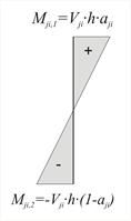 Figure 5.4.3.5-2
 Figure 5.4.3.5-2 - The distribution of shear forces depends only on the geometry of the structural system. This means that if the modulus of elasticity of column material changes, column displacements will also change but shear forces will not.
- The rotation effect increases with the distance of a column from the centre of stiffness, e.g. a column placed at the storey perimeter bears a bigger rotational charge.
- The deformations due to rotation, develop biaxial bending in columns, i.e. simultaneous bending in both directions. Therefore rotation should be limited to the extent possible.
- The biaxial bending of the columns is constantly changing due to the change of directions of seismic forces and displacements. To this end, in contrast to the non-earthquake resistant structures, the exact position of increased reinforcement cannot be predicted, thus it is placed relatively uniformly in the column perimeter.
- Even in geometrically symmetric structures, the accidental eccentricities [*]
 NoteSee Chapter 6. can develop intense biaxial stresses. To this end, high torsional stiffness is extremely useful. High torsional stiffness is mainly obtained from placing strong columns, usually walls, along the building perimeter. NoteSee Chapter 6. can develop intense biaxial stresses. To this end, high torsional stiffness is extremely useful. High torsional stiffness is mainly obtained from placing strong columns, usually walls, along the building perimeter. - The high torsional stiffness is not necessary only in earthquake resistant buildings but also in every building possibly subjected to horizontal actions such as the wind or asymmetrical snow loading or to other unpredictable factors.
- The torsional stiffness of a floor diaphragm depends mainly on the position of the centre of stiffness in relation to the centre of mass, and on the magnitude of the torsional radii. Both factors depend only on the geometry of the structure and not on the magnitude of the seismic loadings.
|