|
« Effective width of flanges [EC2 A§5.3.2.1]
Diaphragmatic function »
|
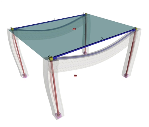
The space model consists of nodes (e.g. node 1, 5, 9 etc.) and bars (e.g. bar 1, 2, 5 etc.). Nodes are symbolic geometric points where bars end.  Figure 3.1.3-1: The real structure and the space model (screen shot captured by the related software)
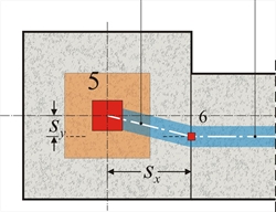
 Figure 3.1.3-1: The real structure and the space model (screen shot captured by the related software) In general, each node has 6 displacements (6 degrees of freedom), three translations δx, δy, δz and three rotations φx, φy, φz. The objective of the analysis is the calculation of the 6 displacements for all nodes. Bars are used for modelling structural elements, beams (e.g. beam b1 is modelled with bar 5) and columns (e.g. column c1 is modelled with bar 1). Thus modelling structural elements of insignificant cross-sections with linear bar elements does not take into consideration two factors: (a) The eccentricities of the beam-to-column supports and (b) The increased stiffnesses around the nodes at beam-to-column junction.  Figure 3.1.3-2: Plan of column-beam nodes: Master node (5) and slave node (6)
 Figure 3.1.3-2: Plan of column-beam nodes: Master node (5) and slave node (6) |  Figure 3.1.3-3: Detail of displaced structure including the rigid body
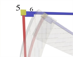
 Figure 3.1.3-3: Detail of displaced structure including the rigid body |
These effects are taken into consideration, using the technique of rigid bodies (rigid offsets). Slave nodes are, therefore, created at the intersection point of the beam axis with the column side face (e.g. node 6) and an ideal rigid body is formed between nodes 5 and 6. Provided the 6 displacements of the master node are δx, δy, δz, φx,φy, φz, the corresponding δx,s, δy,s, δz,s, φ x,s, φy,s, φz,sof the slave node are: δ x,s =δx-sy·φz (given sz=0) δ y,s =δy+sx·φz (given sz=0) In a floor consisting of 20 master and 14 slave nodes, the number of the unknown displacements (degrees of freedom) is equal to 20x6=120.
|
« Effective width of flanges [EC2 A§5.3.2.1]
Diaphragmatic function »
|

|