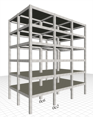
 Figure 6.4.1-1: Structure comprising only columns, project <B_641-1>
 Figure 6.4.1-1: Structure comprising only columns, project <B_641-1>
The six-storey structure illustrated in the figure comprises 12 columns per storey, arranged in grid 5.0 m by 5.0 m. The interstorey height is 3.0 m. In all storeys, the cross-sections of the 10 perimeter and the 2 interior columns are 400/400 and 500/500 respectively. The cross-sections of beams are 250/500, and the thickness of slabs is 150 mm. Consider concrete class C30/37, seismic zone Z1 with agR=0.15g, ground type B, importance class II and ductility class medium.
Four cases are considered:
-
Fixed condition at the ground level
-
Foundation with footing beams
-
Foundation with simple footings
-
Basement with perimeter walls
The main mode shapes of the modal analysis of the first case are illustrated in the following page (similar to the modes of the rest three cases). Then, in the four following pages, the characteristic quantities for all cases are presented.
In the next paragraph 6.4.2 a variation of this structure is considered, but replacing four of the perimeter columns with walls. It is extremely useful to perform a comparison between the cases of both the frame and wall type structure.
General conclusions of the frame system:
1) In all cases only the x horizontal component of the seismic action is considered, the y component produces almost identical results.
2) The natural period of the first mode shape is of the order of 1 sec, while, if the stiffnesses of the elements are taken as being 100% of the elastic, the value of periods is of order of 0.65 sec (see §6.3.3).
3) Apparently the more economical solution of simple footings without strap (connecting) beams eventually becomes the most unfavourable one, even for economic reasons due to the need for additional reinforcement and increased dimensions of beams and columns cross-sections.
4) The best solution is the basement with perimeter walls, i.e. along the 75% of the perimeter, as providing behaviour that better approximates the fixed condition.
5) The bending moments of the two characteristic columns reflect the stress relation between the various cases.
Modal analysis results of the frame type structure
Fixed condition at the ground level (project <Β_641-1>)
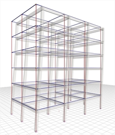 Figure 6.4.1-2: 1st mode in X:
T=0.975 sec, participation 84% Figure 6.4.1-2: 1st mode in X:
T=0.975 sec, participation 84% | 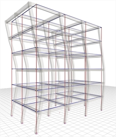 Figure 6.4.1-3: 2nd mode in X:
T=0.321 sec, participation 10% Figure 6.4.1-3: 2nd mode in X:
T=0.321 sec, participation 10% |
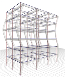 Figure 6.4.1-4: 3rd mode in X:
T=0.189 sec, participation 3.5% Figure 6.4.1-4: 3rd mode in X:
T=0.189 sec, participation 3.5% | 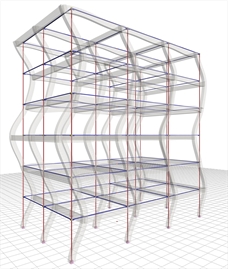 Figure 6.4.1-5: 4th mode in X:
T=0.134 sec, participation 1.6% Figure 6.4.1-5: 4th mode in X:
T=0.134 sec, participation 1.6% |
The sum of the effective modal masses of the first four modes amounts to 99% of the total mass. The first mode is the fundamental one as its effective mass is the 84% of the total mass.
All four modes are translational and not torsional, as expected, due to the double symmetry of the structure.
Case 1: Fixed condition at the ground level (project <Β_641-1>)
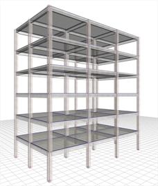 Figure 6.4.1-6: Structure and model
Frame system with q=3.60 Figure 6.4.1-6: Structure and model
Frame system with q=3.60 | 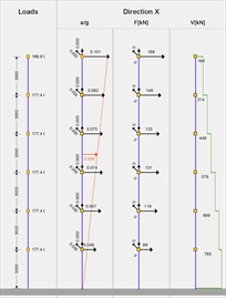 Figure 6.4.1-7: Seismic acceleration-forces-
shear forces. 1st fundamental period:
T1=0.975 sec, participation 84% Figure 6.4.1-7: Seismic acceleration-forces-
shear forces. 1st fundamental period:
T1=0.975 sec, participation 84% |
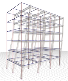 Figure 6.4.1-8: Displacements under
seismic action in x δmax=24.5 mm Figure 6.4.1-8: Displacements under
seismic action in x δmax=24.5 mm | Bending moments of ground floor columns |
 Figure 6.4.1-9:
Ground floor column
0c2 (400/400) Figure 6.4.1-9:
Ground floor column
0c2 (400/400) | 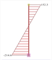 Figure 6.4.1-10:
Ground floor column
0c6 (500/500) Figure 6.4.1-10:
Ground floor column
0c6 (500/500) |
The behaviour factor of the frame system is q=3.60 because the value of au/a1 is taken equal to 1.20.However, the accurate value of au/a1 is 1.30 due to the two-bay frame in y direction, resulting in q=1.30×3.00=3.90 (see §6.1.5.5).
The bending moment of the middle column c6 is roughly twice the value corresponding to the perimeter column, due to its stronger section.
Case 2: Foundation with footing beams (project <Β_641-2>)
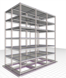 Figure 6.4.1-11: Structure and model.
Frame system with q=3.60 Figure 6.4.1-11: Structure and model.
Frame system with q=3.60 | 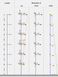 Figure 6.4.1-12: Seismic acceleration-forces-
shear forces.1st fundamental period:
T1=1.012 sec, participation 85% Figure 6.4.1-12: Seismic acceleration-forces-
shear forces.1st fundamental period:
T1=1.012 sec, participation 85% |
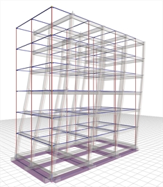 Figure 6.4.1-13: Displacements under
seismic action in x δmax=25.7 mm Figure 6.4.1-13: Displacements under
seismic action in x δmax=25.7 mm | Bending moments of ground floor columns |
 Figure 6.4.1-14:
Ground floor column
0c2 (400/400) Figure 6.4.1-14:
Ground floor column
0c2 (400/400) |  Figure 6.4.1-15:
Ground floor column
0c6 (500/500) Figure 6.4.1-15:
Ground floor column
0c6 (500/500) |
Due to stronger cross-sections of footing beams compared to those of columns, the displacement of the structure is slightly larger than that of assumed fixity at the base (25.7 against 24.5).
The structural system remains intact while the behaviour factor q is taken equal to 3.60.
The bending moments of columns at the footing neck are roughly the same as in the fixed condition.
Case 3: Foundation with simple footings (project <Β_641-3>)
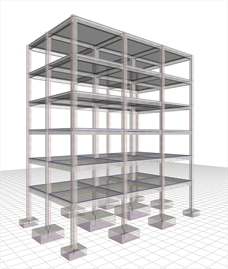 Figure 6.4.1-16: Structure and model.
Torsionally flexible system with q=2.00 Figure 6.4.1-16: Structure and model.
Torsionally flexible system with q=2.00 | 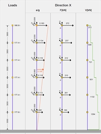 Figure 6.4.1-17: Seismic acceleration-
forces-shear forces.1st fundamental period:
T1=1.075 sec, participation 88% Figure 6.4.1-17: Seismic acceleration-
forces-shear forces.1st fundamental period:
T1=1.075 sec, participation 88% |
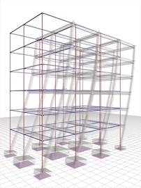 Figure 6.4.1-18: Displacements under
seismic action in x,δmax=47.6 mm Figure 6.4.1-18: Displacements under
seismic action in x,δmax=47.6 mm | Bending moments of ground floor columns |
 Figure 6.4.1-19:
Ground floor column
0c2 (400/400) Figure 6.4.1-19:
Ground floor column
0c2 (400/400) |  Figure 6.4.1-20:
Ground floor column
0c6 (500/500) Figure 6.4.1-20:
Ground floor column
0c6 (500/500) |
In the absence of strap beams, the structure is classified as torsionally flexible system with q=2.00.
The displacement is almost twice that of the strong foundation (47.6 against 25.7 mm).
The bending moments of columns at the ground floor neck are almost twice as those corresponding to the strong foundation.
Case 4: Basement with perimeter walls (project <Β_641-4>)
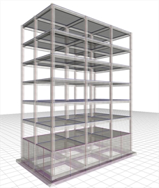 Figure 6.4.1-21: Structure and model.
Frame system with q=3.60 Figure 6.4.1-21: Structure and model.
Frame system with q=3.60 | 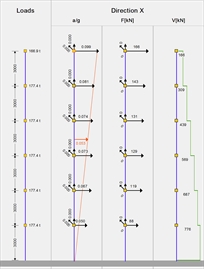 Figure 6.4.1-22: Seismic acceleration-forces-
shear forces.1st fundamental period:
T1=0.999 sec, participation 71% Figure 6.4.1-22: Seismic acceleration-forces-
shear forces.1st fundamental period:
T1=0.999 sec, participation 71% |
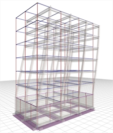 Figure 6.4.1-23: Displacements under
seismic action in x, δmax=25.3 mm Figure 6.4.1-23: Displacements under
seismic action in x, δmax=25.3 mm | Bending moments of ground floor columns |
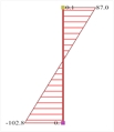 Figure 6.4.1-24:
Ground floor column
0c2 (400/400) Figure 6.4.1-24:
Ground floor column
0c2 (400/400) | 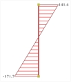 Figure 6.4.1-25:
Ground floor column
0c6 (500/500) Figure 6.4.1-25:
Ground floor column
0c6 (500/500) |
The overall behaviour of the structure is better than the one corresponding to the strong foundation at the ground floor, approaching that for assumed fixity at the base.