Multistorey plane frame systems
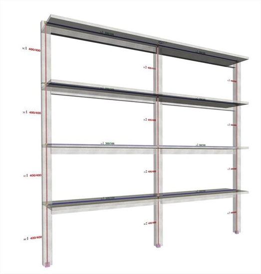
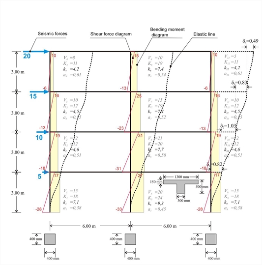
The following project <B_531> of a multistorey plane frame shows the interstorey fluctuation of the apparent stiffness factor kj and the moment distribution factor aj in both middle and end columns.
The apparent stiffness factors kj vary from 4 to 9, while the moment distribution factors aj from 0.40 to 0.60.
The apparent stiffnesses are independent of the seismic force magnitude. They depend only on the distribution of forces along the height of the frame. To this end, in the following examples, both forces, shear forces, bending moments, and deformations are unitless.
 Figure 5.3.1-1: Four-storey frame type structure comprising three columns
 Figure 5.3.1-1: Four-storey frame type structure comprising three columns
In case of a basement, seismic forces developed at its roof level have a zero value. However, fixed end condition applies only to the base of the columns along the basement perimeter walls.
If the frame also comprises walls, as presented in the following paragraph, the stiffnesses and the moment distribution of the walls differ between them. This difference becomes more distinctive as the number of stories increase.
The total joint displacements and column stress resultants (shear forces and bending moments) are obtained from the frame analysis. Quantities K, k and a derive from the previous results. The apparent stiffness Ki of storey i derives from the expression Ki=Vi/δi, while the apparent stiffness of column j of storey i from the expression Ki,j=Vi,j/δi.
 Figure 5.3.1-2: Column frame type structure with triangular distribution of seismic forces(practical graphical representation)
 Figure 5.3.1-2: Column frame type structure with triangular distribution of seismic forces(practical graphical representation)
Example 5.3.1 (3rd storey) :
Column stiffnesses: K3,1=9.6/0.823=12, K3,2=15.8/0.823=19, K3,3=9.6/0.823=12.
Storey stiffness: Κ 3 = (20+15)/0.823=43. The same value is obtained if calculated as the summation of the column stiffnesses of the storey, i.e. K3= K 3,1+K3,2+ K3,3=43.
If shear effect is taken into account (Shear effect=ON), the displacements are δ 1 =0.85, δ 2 =1.05, δ 3 =0.84, δ 4 =0.50 mm, i.e. the difference is insignificant.
If rigid bodies effect is taken into account (Rigid body=ON), the displacements are δ 1 =0.80, δ 2 =0.97, δ 3 =0.77, δ 4 =0.45 mm, i.e. both decrease of displacements and increase of stiffnesses are small but measurable.