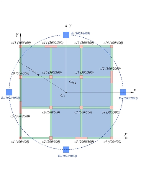
In the floor of exercise 5.4.7-1 above, calculate the corresponding results if the columns C3, C5, C12, C14 are replaced by walls with cross-section 2000/300 parallel to each perimeter side.  Figure 5.4.7.3
 Figure 5.4.7.3 The displacement of the center of stiffness CT is δxo=2.01 mm. The maximum primary and secondary displacements are δxx=2.27 mm (2.27/2.01=113 %) and δxy=0.26 mm (0.26/2.01=13 %) respectively, whereas the minimum values are δ xx=1.76 mm (1.76/2.01=88 %) and δxy=0.09 mm (0.09/2.01=4%) respectively. rx=9.41 m, ry=9.41 m (E=1003/1003), θz= -0.00003409, Kθ=87.993.0 MN·m The above analysis has been carried-out performed with the option «Shear effect» activated. If shear effect is not taken into account, the displacement of the center of stiffness CT would be δxo=1.84 mm (2.01/1.84=109 %). - In the presence of walls, the shear effect should be taken into account, because they affect significantly both the displacements magnitude and the stress resultants distribution.
- The magnitude of the maximum displacement is equal to 2.27 mm compared to 5.60 mm of the frame type structure of exercise 5.4.7-1 thus requiring smaller seismic joints, when necessary. The resulting wall displacements are smaller leading to less important or nil damages in the event of an earthquake. Moreover smaller stresses are developed in the columns and less reinforcement is required.
|