Two examples are analysed applying the general method on the same simple structure of Appendix C.1. The choice of a simple structure is useful for easy monitoring of the results and the comprehension of the diaphragmatic floor behaviour of floors. In the one-storey structure of project <B_d9-1> the two translations of node 5 (column C1) and the diaphragm rotation θ XZ should be calculated, using either the related software or any other relevant software. Optionally, the translations of the remaining points of the diaphragm may be calculated. All diaphragm data can derive based on these displacements. 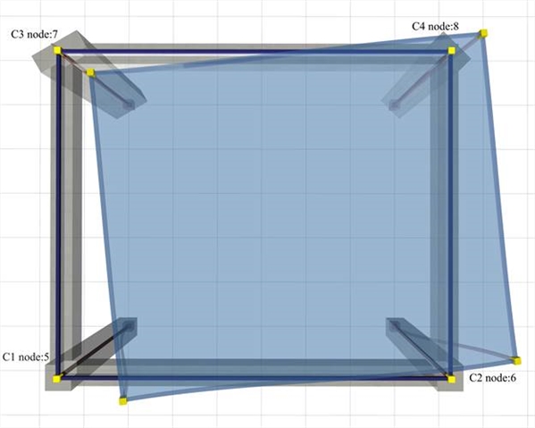 Figure D.7.1-1: The simple structure of 4 columnsC1:400/400, C2:400/400, C3:800/300 φ=30º, C4:300/600 φ=45º, h=3.0 m, beams 250/500
 Figure D.7.1-1: The simple structure of 4 columnsC1:400/400, C2:400/400, C3:800/300 φ=30º, C4:300/600 φ=45º, h=3.0 m, beams 250/500 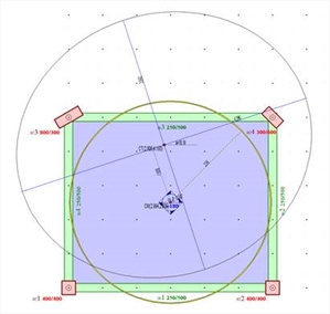 Figure D.7.1-2: Output image of the software
 Figure D.7.1-2: Output image of the software
The mass inertial ring is the same as in the previous case, since it depends only on the loads. However all other results are different, as expected. The values of the coordinates of the centre of stiffness CT are (2.806, 4.193), and the torsional radii arerx=4.390 m, ry=3.842 m versus the values 2.688, 4.897, rx=4.411 and ry=3.381 obtained from the assumption of fixed-ended columns in Appendix C. All results are displayed in detail by selecting from the menu “View” and then “Diaphragm results”, “report”. θXZ =11.952·10-5. The remaining results are better displayed in 3D, by selecting from the menu “View”, “Diaphragm results”, “3D floor” combined with “free rotation analysis” or “fixed rotation analysis” or “rotation only”, as presented in the two following pages. In the one-storey structure considered the “only rotation” condition can derive directly from the analysis by applying only moment as external loading, the reason being that the centre of stiffness CT in one-storey diaphragms remains, by definition, stationary with respect to the ground. Calculation [*] Note The software performs the calculations of the diaphragm automatically. The verification of the algorithms using the software tools is presented here. of the diaphragmatic behaviour Note The software performs the calculations of the diaphragm automatically. The verification of the algorithms using the software tools is presented here. of the diaphragmatic behaviour 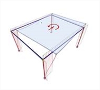 Figure D.7.1-3
 Figure D.7.1-3 |  Figure D.7.1-4
 Figure D.7.1-4 |  Figure D.7.1-5
 Figure D.7.1-5 | | | Loading 2 : HX=90.6 kN
Diaphragm restrained against rotation | Loading 3 : HY=90.6 kN
Diaphragm restrained against rotation | 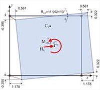 Figure D.7.1-6
 Figure D.7.1-6 | 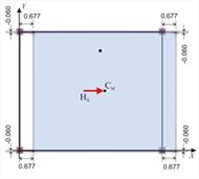 Figure D.7.1-7
 Figure D.7.1-7 | 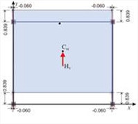 Figure D.7.1-8
 Figure D.7.1-8 | | Analysis results: The translations of point 1 are δ XX1 =1.178, δ XY1 =-0.395mm and the diaphragm rotation is
θ XZ =11.952 ·10-5 | Analysis results: The diaphragm develops only parallel translations in X,Y directions, being restrained against rotation. Thus all diaphragm points (including CT) develop the same displacements: δ XXo =0.677 mm , δ XYo =-0.060. | Analysis results: The diaphragm develops only parallel translations in X,Y directions, being restrained against rotation, which are: δ YXo =-0.0600, δ YYo =0.839 mm
The angle of the principal system derives from the expression:
tan(2a)=2 δ XYo /( δΧΧο - δ YYo )=
=2 ·(-0.060)/(0.677-0.839)= =0.741 → 2a=36.5° → a=18.2° |
Calculation of the diaphragmatic behaviour (continued) 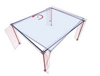 Figure D.7.1-9
 Figure D.7.1-9 | 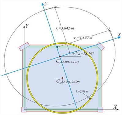 Figure D.7.1-10
 Figure D.7.1-10 | | Loading 1 minus loading 2: HX=0, MXCT=90.6 · (YCT- YCM ) +90.6 | 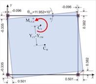 Figure D.7.1-11
 Figure D.7.1-11 | | Subtraction results: The diaphragm only rotates by θ XZ about the centre of stiffness CT. The translations of the first point due to rotation:
δ Xt,1 = δ X,1 - δ XXo =1.178-0.677 =0.501 mm,
δ Yt,1 = δ Y,1 - δ XYo =-0.395+0.060 =-0.335mm and XCT=X1- δ Yt,1 / θ XZ = =0.0+0.335 ·10-3 /11.952 ·10-5 =2.803 m YCT =Y1+ δ Xt,1 / θ XZ = 0.0+0.501 ·10-3 /11.952 ·10-5 =4.192 m | Determination of stiffnesses and torsional radii : The lateral stiffnesses Kxx, Kyy are calculated using the expressions C.9.2 and C.9.3 of §C.9, with a=18.186° and tana=0.329:
Kxx=H/(δXXo+δXYo·tana)=[90.6/(0.677-0.060·0.329)]· 106N/m=
= 137.8·106 N/m
Kyy=H/(δYYo-XYo·tana)=[90.6/(0.839+0.060·0.329)]·10 6N/m=
=105.5·106 N/m MXCT [*] NoteMoment, rotation and torsional stiffness Kθ have the same values in both the initial system X0Y and the principal system xCTy. It is preferable to work in the initial system, as the calculations are simpler. =90.6 · ( Υ CT -YCM)+90.6 · cY=90.6 ·(4.193-2.509)+90.6·1.0= NoteMoment, rotation and torsional stiffness Kθ have the same values in both the initial system X0Y and the principal system xCTy. It is preferable to work in the initial system, as the calculations are simpler. =90.6 · ( Υ CT -YCM)+90.6 · cY=90.6 ·(4.193-2.509)+90.6·1.0=
=243.2 kNm,
K θ = MXCT/ θ XZ =243.2/11.952 ·10-5=20.3·105 kNm
rx=√K θ /Kyy=√[20.3·108Nm/105.5·106N/m]=4.39 m
ry=√K θ /Kxx=√[20.3·108Nm/137.8·106N/m]=3.84 m | The expressions determining the CT coordinates are general and they apply to any point of the diaphragm. For instance, from column 4: XCT=X4-δYt,4/θXZ=6.0-0.382·10-3m/11.952·10-5=6.0-3.20=2.80 m YCT=Y4+δXt,4/θXZ=5.0-0.096·10-3m/11.952·10-5=5.0-0.80=4.20 m 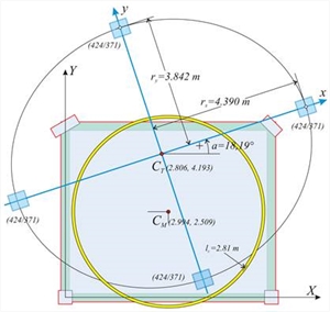 Figure D.7.1-12: Equivalent system of 4 columns of 424/371 cross-section (at the “ Equivalent system” field enter k=1 n=4k=4)
 Figure D.7.1-12: Equivalent system of 4 columns of 424/371 cross-section (at the “ Equivalent system” field enter k=1 n=4k=4) | In this example considered, since the structure is one-storey (the same applies to the ground floor of any multistorey building), the torsional stiffness ellipse of the equivalent system is identical to that corresponding to the actual floor. Selecting “Equivalent system/Draw”=ON, the torsional stiffness ellipse, verified previously, with the 4 equivalent columns of 424/373 cross-section located on its vertices, are displayed by the software (see figure D.7-12). The equivalence of these 4 fixed-ended columns is checked next: | The calculations are effected in the principal coordinates system, where each column stiffness in its local system, is the same with that of theprincipal. Kx=12Ε·Ιx/h3 and Kx=12Ε·Ιy/h3 (see §5.1.1), since in the example considered the shear effect, in any case insignificant had been ignored, and therefore kva=1. Ix= 0.373·0.4243/12= 23.693 ·10-4 m4, Iy= 0.424 ·0.3733/12=18.336·10-4 m4 Given E=32.8 GP and h=3.0 m → Kx=12·32.8·109Pa·23.693· 10-4m4/3.03m3=34.54·106 N/m Ky=12 · 32.8 · 109 Pa · 18.336 · 10-4m4/3.03m3=26.73·106 N/m For 4 equivalent columns→ Kxx=Σ(Kx)=4·34.54=138.2·106 N/m, Kyy= Σ (Ky)=4·26.73=106.9·106 N/m , Therefore equal to the actual stiffness (slight differences are justified by the need to use integer mm). The torsional stiffness of the equivalent diaphragm is Kθ=Σ(Kxi·yi2+Kyi·xi2+0.0) (expression 7, §C.5) → Kθ=2·Κx·3.8422+2·Ky·4.3902=2·34.54·106N/m·14.76m2 + 2·26.73· 106N/m·19.271m2= (10.2+10.3)·105 kNm =20.5·105 kNm , therefore equal to the actual torsional stiffness. It is obvious that rx, ry values are also identical, being equal to thesquare root of the ratio of equal quantitiesrxΖ=√(Kθ /Kyy)=4.39 m, ryΖ=√(Kθ/Kxx)=3.84 m. The equivalent building may comprise only 4 columns, or any number of columns n=4k, where κ is nonzero integer, e.g. 4, 8, 12, 16, 20, … These columns by groups of four, are placed symmetrically with respect to the centre of stiffness. For instance, the case of 8 columns of 356/312 cross-section, yields: Ix= 0.312·0.3563/12= 11.731 ·10-4 m4, Iy= 0.356 ·0.3123/12=9.010·10-4 m4 Given E=32.8 GP and h=3.0 m → Kx=12·32.8·109Pa·11.731·10-4m4/3.03m3=17.01·106 N/m, Ky=12·32.8·109Pa·9.010· 10-4m4/3.03m3=13.13·106 N/m. For 8 equivalent columns → Kxx=Σ(Kx)=8·17.01=136.8·106 N/m and Kyy= Σ(Ky)=8·13.13=105.1·106 N/m. To calculate the torsional stiffness, the coordinates (±3.105 m, ±2.717 m) of the 4 intermediate points are used, which are displayed both at the screen and in the “report” (if “coords” selected). Alternative equivalent structures 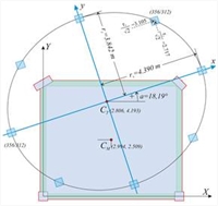 Figure D.7.1-13: Case of 8 columns (k=2, n=4k=8)of 356/312 equivalent cross-section
 Figure D.7.1-13: Case of 8 columns (k=2, n=4k=8)of 356/312 equivalent cross-section | 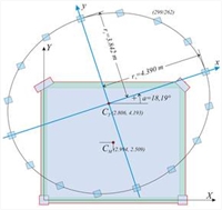 Figure D.7.1-14: Case of 16 columns (k=4, n=4k=16)of 299/262 equivalent cross-section
 Figure D.7.1-14: Case of 16 columns (k=4, n=4k=16)of 299/262 equivalent cross-section | 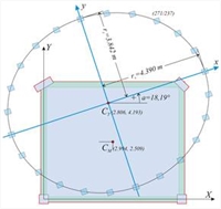 Figure D.7.1-15: Case of 24 columns (k=6, n=4k=24)of 271/237 equivalent cross-section
 Figure D.7.1-15: Case of 24 columns (k=6, n=4k=24)of 271/237 equivalent cross-section | 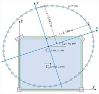 Figure D.7.1-16: Case of 48 columns (k=12, n=4k=48)of 227/199 equivalent cross-section
 Figure D.7.1-16: Case of 48 columns (k=12, n=4k=48)of 227/199 equivalent cross-section |
K θ = Σ (Kxi · yi2+Kyi · xi2)= 2 · Κ x · 3.8422+4 · Κ x · 2.717 2 +2 · Ky · 4.3902+4 · Ky · 3.1052= =[17.01 ·(29.52+29.53)+13.13·(38.54+38.56)]·103 kNM=[10.1+10.1]·105 kNM =20.2·105 kNM Thus, the system of 8 fixed-ended columns is also equivalent to the actual structure. In this way all systems with n=4k are verified to be equivalent to the initial actual structure. In the three-storey structure of project <B_d9-2> using the related software or any other relevant software, for each of the three loadings in this particular example the two translations of node 9 (column C1) and the rotation of the diaphragm of level 2 are calculated. Optionally, the translations of the other diaphragm points may be calculated. All diaphragm data are computed based only on the displacements of node 9. 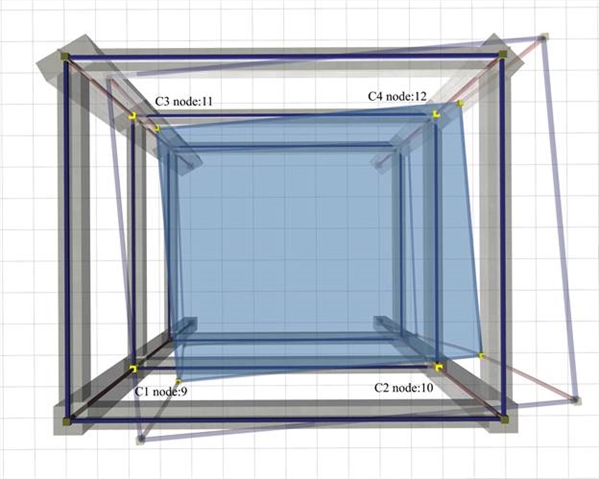 Figure D.7.2-1: The simple structure of 3 storeys and 4 columns.The floor is typical, identical to the floor of first example
 Figure D.7.2-1: The simple structure of 3 storeys and 4 columns.The floor is typical, identical to the floor of first example
After entering into “Element Input”, select “Tools” from the menu and then “Diaphragm calculation”. In the dialog opened, enter H=90.6 kN, c Y=1.0 m, select “Use fixed columns=OFF” and press “ΟΚ” and the diaphragm data of the current floor are displayed. Floor 1, that corresponds to level 2 is then selected.. 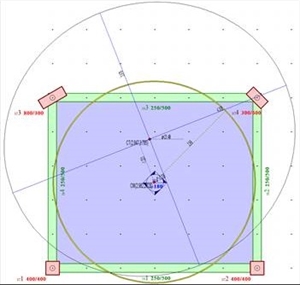 Figure D.7.2-2: Output image of the software
 Figure D.7.2-2: Output image of the software
The coordinates of the centre of stiffness C T are ( 2.847, 3.785), and the torsional radii are rx=4.305 m, ry=3.979 m (versus the coordinates 2.688, 4.897, rx=4.411 and ry=3.381 derived by the assumption of fixed-ended columns). The cross-section of the equivalent columns is 335/321 (versus 521/399 derived by the assumption of fixed-ended columns). All results are displayed analytically by selecting from the menu “View”, “Diaphragm results”, “report”. In level 2 θXZ =30.2962·10-5. The rest of results are better displayed in 3D, by selecting from the menu “View”, “Diaphragm results”, “3D floor” combined with “free rotation analysis” or “ restrained rotation analysis” or “rotation only”, as presented in the two following pages. In the structure considered, being multistorey, the “only rotation” condition of a diaphragm, i.e. with CT remaining stationary with respect to the ground, may only derive using the trick of the following general method,.
Calculation of the diaphragmatic behaviour of level 2 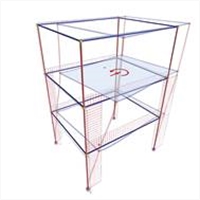 Figure D.7.2-3
 Figure D.7.2-3 |  Figure D.7.2-4
 Figure D.7.2-4 |  Figure D.7.2-5
 Figure D.7.2-5 | Loading 1 : HX=90.6 kN with loading eccentricity cY=1.0 m resulting in moment MXCM=90.6 kNm | Loading 2 : HX=90.6 kN
Diaphragm restrained against rotation | Loading 3 : HY=90.6 kN
Diaphragm restrained against rotation | 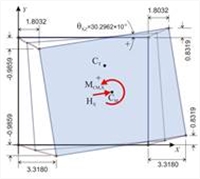 Figure D.7.2-6
 Figure D.7.2-6 | 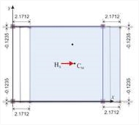 Figure D.7.2-7
 Figure D.7.2-7 | 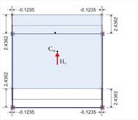 Figure D.7.2-8
 Figure D.7.2-8 | | Analysis results: The translations of point 1 are δ XX1 =3.318, δ XY1 =-0.986mm and the diaphragm rotation is
θ XZ =30.2962 ·10-5 | Analysis results: The diaphragm develops only parallel translations in X,Y directions, being restrained against rotation. Thus all diaphragm points (including CT) develop the same displacements:
δ XXo =2.1712 mm, δ XYo =-0.1235 | Analysis results: The diaphragm, being restrained against rotation, develops only parallel translations in X,Y directions, which are:
δ YXo =-0.1235, δ YYo =2.4362 mm
The angle of the principal system derives from the expression:
tan(2a)=2 δ XYo /( δΧΧο - δ YYo )=
2 ·(-0.1235)/(2.1712-2.4362)= 0.932 → 2a=43.0° → a=21.5° |
Calculation of the diaphragmatic behaviour of level 2 (continued)
 Figure D.7.2-9
 Figure D.7.2-9 | 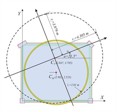 Figure D.7.2-10
 Figure D.7.2-10 | | Loading 1 minus loading 2: HX=0, MXCT=90.6 · (YCT- YCM ) +90.6 | 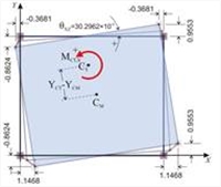 Figure D.7.2-11
 Figure D.7.2-11 | | Subtraction results: The diaphragm only rotates by θ XZ about the centre of stiffness CT. The translations of the first point due to rotation: δ Xt,1 = δ X,1 - δ XXo =
=3.3180-2.1712 =1.1468,
δ Yt,1 = δ Y,1 - δ XYo =
=-0.9859+0.1235 =-0.8624 and XCT=X1- δ Yt,1 / θ XZ = 0.0+0.8624 ·10-3 /30.2962 ·10-5 =2.847 m YCT =Y1+ δ Xt,1 / θ XZ = 0.0+1.1468 ·10-3 /30.2962 ·10-5 =3.785 m | Determination of stiffnesses, torsional radii and equivalent system : The lateral stiffnesses Kxx, Kyy are calculated using the expressions C.9.2 and C.9.3 of §C.9 with a=21.49° → tana=0.393:
Kxx=H/(δXXo+δXYo·tana)= =[90.6/(2.1712-0.1235·0.393)]·106N/m= 42.7·106 N/m
Kyy=H/(δYYo-XYo·tana)= =[90.6/(2.4362+0.1235·0.393)]·106N/m= 36.5·106 N/m MXCT=90.6 · ( Υ CT -YCM)+90.6 · cY=90.6 ·(3.785-2.525)+90.6·1.0=
204.8 kNm,
K θ = MCT,X/ θ XZ =204.8/30.2962 ·10-5=6.759·105 kNm
rx=√K θ /Kyy=√[6.759·108Nm/36.5·106N/m]=4.30 m
ry=√K θ /Kxx=√[6.759·108Nm/42.7·106N/m]=3.98 m | The expressions determining the CT coordinates are general and they apply to any point of the diaphragm. For instance, from column 4: XCT=X4-δYt,4/θXZ=6.0-0.9553·10-3m/30.2962·10-5=6.0-3.153=2.847 m YCT=Y4+δXt,4/θXZ=5.0-0.3681·10-3m/30.2962·10-5=5.0-1.215=3.785 m 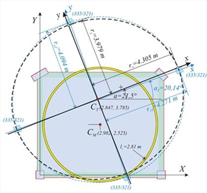 Figure D.7.2-12: Equivalent diaphragm of level 2 with 4 columns of 335/321 cross-section (at the “ Equivalent system” field enter k=1 n=4k=4)
 Figure D.7.2-12: Equivalent diaphragm of level 2 with 4 columns of 335/321 cross-section (at the “ Equivalent system” field enter k=1 n=4k=4) | The equivalent system of the three-storey building comprises three diaphragms, equivalent to the actual ones. The results for both the actual and the equivalent diaphragms are given in the “report” of the related software. The two following tables of the equivalent diaphragms are taken from the report. |
Equivalent system displacements | Elevation | dXXo,i
mm | dXYo,i
mm | qXZM,i
1.0e-5 | dYYo,i
mm | dXXoZ,i
mm | dXYoZ,i
mm | dYYoZ,i
mm | qXZMZ,i
1.0e-5 | | 1 | 0.612 | -0.079 | 4.2009 | 0.773 | 0.612 | -0.079 | 0.773 | 4.2009 | | 2 | 2.171 | -0.123 | 13.4045 | 2.436 | 1.559 | -0.044 | 1.663 | 9.2036 | | 3 | 4.198 | -0.072 | 24.6910 | 4.437 | 2.026 | 0.052 | 2.001 | 11.2865 | Equivalent system cross-sections | Elevation | hi
m | αZ,i
deg | MXM,i
KNm | KqZ,i
MNm | KxxZ,i
MN/m | KyyZ,i
MN/m | rxZ,i
m | ryZ,i
m | AxZ,i
mm | AyZ,i
mm | | 1 | 3.00 | 22.3069 | 90.60 | 2156.7 | 156.30 | 112.45 | 4.379 | 3.715 | 441 | 374 | | 2 | 3.00 | 20.1371 | 90.60 | 984.4 | 58.72 | 53.95 | 4.271 | 4.094 | 335 | 321 | | 3 | 3.00 | 38.0593 | 90.60 | 802.7 | 43.83 | 46.21 | 4.168 | 4.279 | 306 | 314 | Verification of the tabulated results using the theory presented in §D.6: δ XXo Ζ ,1 = δ XXo,1 -0.0=0.612 , δ XYo Ζ ,1 = δ XYo,1 -0.0=-0.079, δ YYo Ζ ,1 = δ YYo,1 -0.0=0.773, θ XZ Μ Z,1 = θ X ΖΜ ,1 –0.0=4.2009 δ XXo Ζ ,2 = δ XXo,2 - δ XXo,1 =2,171-0.612=1.559, δ XYo Ζ ,2 = δ XYo,2 - δ XYo,1 =-0.123-(-0.079)=-0.044
δ YYo Ζ ,2 = δ YYo,2 - δ YYo,1 =2.436-0.773=1.663, θ XZ Μ Z,2 = θ X ΖΜ ,2 – θ XZ Μ ,1 =13.4045-4.2009=9.2036 δ XXo Ζ ,3 = δ XXo,3 - δ XXo,2 =4.198-2.171= 2.026, δ XYo Ζ ,3 = δ XYo,3 - δ XYo,2 =-0.072-(-0.123)=0.051
δ YYo Ζ ,3 = δ YYo,3 - δ YYo,2 =4.437-2.436=2.001, θ XZ Μ Z,3 = θ X ΖΜ ,3 – θ XZ Μ ,2 =24.6910-13.4045=11.2865 Diaphragm data for all levels derive from these quantities, therefore specifically for level 2: tan(2az,2)=2 · δ XYo Ζ ,2 /( δ XXo Ζ ,2 - δ YYo Ζ ,2 )=2 · (-0.044)/(1.559-1.663) → tan(2az,2)=0.8462 → az,2=20.12º and tanaz,2=0.3667 K θ Z,2 = ΜΧΜ ,2 / θ XZ Μ Z,2 =90.6 ·1.0/ 9.2036=984.4, KxxZ,2= H/( δ XXoZ,2 + δ XYoZ,2 · tanaZ,2)=90.6/(1.559+(-0.044) · 0.3667)=58.7 and Kyy Ζ ,2 =H/( δ YYoZ,2 - δ XYoZ,2 · tanaZ,2)=90.6/(1.663-(-0.044) ·0.3667)=53.95 rxZ,2=√K θ Z,2 /KyyZ,2=√(984.4/53.95)=4.27, ryZ,2=√K θ Z,2 /KxxZ,2 =√(984.4/58.72)=4.094 quod erat demonstrandum .
[1] If “fixed columns=ON” then the results are based on the assumption of fixed-ended columns and the results are identical with those of the first two cases. The slight differences in the results versus the ones obtained by the manual calculations, as well as the ones resulting from the excel file are due to the small differences of the centre of mass, due to the uneven loads from the columns self-weight. [2] The software performs the calculations of the diaphragm automatically. The verification of the algorithms using the software tools is presented here. [3] The horizontal seismic force acts on the centre of mass CM. The loading eccentricity, cy=1.0, may also be given as equivalent moment MCM,X=HX·cY. In this case MCM,X=90.6·1.0=90.6 kNm. This additional eccentricity increases the effect of rotation producing larger translations due to rotation, thus leading to a more accurate calculation of diaphragm torsional data. Besides that, the moment induced by the eccentricity moment provides solutions even in cases that the centres of mass and stiffness are close or coincide. [4] Moment, rotation and torsional stiffness Kθ have the same values in both the initial system X0Y and the principal system xCTy. It is preferable to work in the initial system, as the calculations are simpler.
|