FORMWORK OF THE FOUNDATION and the basement floor (Drawing C.20)
Upon the surface of the leveling concrete, one must mark (a) the columns, (b) two points of every axis x0,x1, …,y0,y1,… , (c) the sides of the strip foundation and shear walls as well as the footings’ sides of the strip or the spread footings foundation. This can be done by means of a thick pencil, a special marker pen, steel pins or small wooden laths (which will be removed prior to the concrete casting), or by means of any other way.
It is recommended to temporarily define xi and yj axes either naturally (with properly fitted strings, in Greece these are called “stitches”) or electronically, so as to facilitate the determina-tion/confirmation of the remaining points and axes.
Specialized topographic personnel must determine at least the fixed points; however the lining must be confirmed with properly fitted strings and a surveyor’s tape, both by the supervisor en-gineer and by the contractors responsible for the structural frame’s erection.
When the elevator stops at the basement, its foundation must be placed around 1.40m lower than the basement level. The most effective way of construction is to normally implement the reinforcement of the elevator’s foundation together with the rest of the foundation reinforcement and before any formwork assembling, to concrete only the spread footing of the elevator. Later this will help in the proper and well-balanced positioning of the elevator’s shear wall moulds and in securing the accurate continuation of the available working space at the other floors.
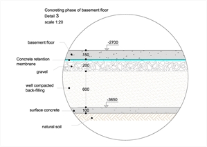
 Detail of the drawing C.20
 Detail of the drawing C.20
All the channels required for the piping placement of every type of installation e.g. drainage must be opened and covered prior to the final filling layer and at least before the compaction and the formation of the final surface. The installations of the foundation’s floor must be pre-sented in a separate drawing in every detail. Extra attention must be paid when defining and presenting the required vertical holes in the foundation beams for the positioning of the installa-tion pipes.
The concrete grate of the basement floor must be the same as the one used for the structural frame because it also covers the columns’ and shear walls’ layer (see §3.7.5).
All concrete surfaces must be thoroughly cleaned and washed prior to the concreting of the basement’s floor. In the peripheral shear walls it is possible to use an adhesive emulsion, which will be placed after the meticulous cleaning and right before the concreting (see and the rele-vant detail in drawing C.30).
During an earthquake, the building’s sway up to the basement’s ceiling is considered zero and therefore, there is no obligation for a joint at the foundation and the basement. However, its po-sition must be indicated in these drawings because the reinforcement of the columns’ and shear walls’ must have the proper layout in order to be connected with the reinforcement of the corre-sponding vertical elements of the ground floor and the upper storeys.