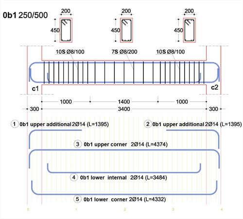
The following figure shows one beam supported by two columns.
This beam, due to its flexibility and the loads that it bears (self weight, supported slab, walls, etc), is deformed by the way mentioned in chapter 1.4.2 The reinforcement placed inside beams consists of the longitudinal bars and the transverse reinforcement in the form of stirrups (ties).
The longitudinal rebars are placed in order to resist the flexural tensile stresses that appear along the beam axis while stirrups are used to carry the diagonal tensile stresses caused by shear.
Moreover, stirrups help in the confinement of longitudinal reinforcement in critical areas.
 Details of longitudinal rebars in characteristic areas of the beam
 Details of longitudinal rebars in characteristic areas of the beam
The number placed in front of the beam b1 indicates the floor that this beam belongs to. In this case, it is number 0 which corresponds to the ground floor [*] Notein places where the first floor above ground is not referred to as ground floor but as 1st floor, number 1 represents the ground floor and the beams’ number prefix is …,-2,-1,1,2,3,… . 1 represents the 1st floor, 2 the 2nd floor, -1 the first basement and so on. This means that the beams’ number prefix is …,-2,-1,0,1,2,…
Since most of the times beams with names b1, b2 etc appear in all floors, it is compulsory to use the prefix both in the constructional drawings and in the beams’ labels so as to avoid confusion with the drawings and the various materials used (these are specified in the beam’s labels).
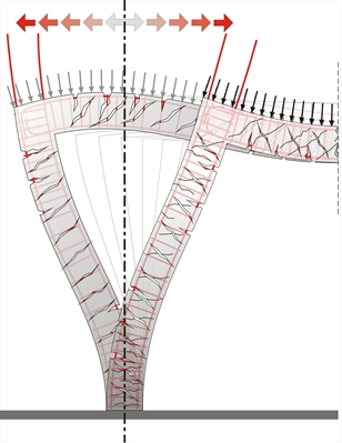
 A seismic ground motion causes reverse bending moments to the beam.
 A seismic ground motion causes reverse bending moments to the beam.
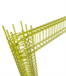
 In the joint area of an earthquake resistant frame both the upper and the lower reinforcement are fully anchored.
 In the joint area of an earthquake resistant frame both the upper and the lower reinforcement are fully anchored.
The stirrups hold the rebars in place and they carry the diagonal tensile forces that usually shift direction.
The beam’s region next to the face of the column is characterized as ‘critical’ because it carries the largest stresses. Its length is equal, from 1 to 1.5 times, the depth of the beam (in our example was assumed as 2*0,50=1.00 m). The stirrups placed at the critical areas must be narrow spaced and properly closed.
The required anchorage length for the lower fibers of the beams is 30% smaller in comparison to that required for the upper fibers of the beams. This is the reason that in finishing nodes, the lower beam reinforcement bars are anchored with a smaller hook. Additionally, in order to create more space for the concreting process, the lower reinforcement bars are shorter than the upper bars, as shown in the beam reinforcement details.
The beams’ width must be greater or equal to 200 mm and at least 2Ø14 must go through the full length of the beam both at the top as well as at the bottom.