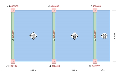
Given : Covering load ge=1.00 kN/m2, live loads of domestic use q1=q2=2.00 kN/m2, q3=5.00 kN/m2, concentrated load applied at the free end of the cantilever G3=1.00 kN/m.
Question : Perform static analysis for the slabs illustrated in the figure (a) under global loading and (b) taking into account the effect of live loads.
 Figure 4.9.3-1: Project <Β_49-3>
 Figure 4.9.3-1: Project <Β_49-3>
Self-weight: go=0.16m·25.0kN/m3=4.00 kN/m2
Covering load: ge= 1.00 kN/m2
Total dead load: g= 5.00 kN/m2
In ULS, the minimum design load for each slab i is equal to gd,i=1.00·g, whereas the total design load is equal to pd,i=γg·gi+γq·qi. In this case gd,i=1.00x5.00=5.0 kN/m and Gd,3=1.00x1.0 kN (concentrated load). The maximum design load for the first two slabs is equal to pd,1=pd,2=1.35x5.00+1.50x2.00=9.75 kN/m, while for the third slab (balcony) is equal to pd,3=1.35x5.00+1.50x5.00=14.25 kN/m και Pd,3=1.35x1.00=1.35 kN.
ULS design load is applied simultaneously on each slab.
.jpg?bhow=0&w=500&h=500&Str=0) Figure 4.9.3-2
Figure 4.9.3-2 Figure 4.9.3-2
(B) Unfavourable loadings
.jpg?bhow=0&w=350&h=350&Str=0) Figure 4.9.3-3
Figure 4.9.3-3 Figure 4.9.3-3
For each loading case the expressions giving the solution are identical:
V21=-p2·l12/2+(M2-M1)/l12
.jpg?bhow=0&w=320&h=320&Str=0) Figure 4.9.3-4
Figure 4.9.3-4 Figure 4.9.3-4
M10=-p1·l012/8=-9.75x4.02/8=-19.50 kNm
M2=-p3·l232/2-P3·l23=-14.25x1.452/2-1.35x1.45=-16.94 kNm
M12=-p2·l122/8-M2/2=-9.75x4.02/8+16.94/2=-11.03 kNm
M1=(M10+M12)/2=-(19.50+11.03)/2=-15.27 kNm
V01=p1·l01/2+M1/l01=9.75x4.0/2-15.27/4.0=19.50-3.82=15.68 kN
V10=-p1·l01/2+M1/l01=-9.75x4.0/2-15.27/4.0=-19.5-3.82=-23.32 kN
V12=p2·l12/2+(M2-M1)/l12=9.75x4.0/2+(-16.94+15.27)/4.0=19.50-0.42=19.08 kN
V21=-p2·l12/2+(M2-M1)/l12=-9.75 x4.0/2+ (-16.94+15.27)/4.0=-19.50-0.42=-19.92 kN
V23=p3·l23+P3=14.25 x1.45+1.35=20.66+ 1.35=22.01 kN, V32=P3=1.35 kN
maxM01=V012/(2·p1)=15.682/(2x9.75)=12.61 kNm, maxM12=V122/(2·p2)+M1= 19.082/(2x9.75)-15.27=3.40 kNm
UNFAVOURABLE LOADINGS ANALYSIS
1st loading case : maxΜ01, minM12
.jpg?bhow=0&w=320&h=320&Str=0) Figure 4.9.3-5
Figure 4.9.3-5 Figure 4.9.3-5
M10=-p1·l012/8=9.75x4.02/8=-19.50 kNm
M2=-p3·l232/2-P3·l23=-14.25x1.452/2-1.35x1.45=-16.94 kNm
M12=-p2·l122/8-M2/2=-5.00x4.02/8+16.94/2=-1.53 kNm
M1=(M10+M12)/2=-(19.50+1.53)/2=-10.52 kNm
V01=p1·l01/2+M1/l01=9.75x4.0/2-10.52/4.0=19.50-2.63=16.87 kN
V10=-p1·l01/2+M1/l01=-9.75x4.0/2- 10.52/4.0=-19.50-2.63=-22.13 kN
V12=p2·l12/2+(M2-M1)/l12=5.00x4.0/2+ (-16.94+10.52)/4.0=10.00-1.61=8.39 kN
V21=-p2·l12/2+(M2-M1)/l12=-5.00x4.0/2+ (-16.94+10.52)/4.0=-10.00-1.61=-11.61 kN
V23=p3·l23+P3=14.25x1.45+1.35=20.66+1.35=22.01 kN, V32=P3=1.35 kN
maxM01=V012/(2·p1)=16.872/(2x9.75)= 14.59 kNm
maxM12=V122/(2·p2)+M1=8.392/(2x5.00 )-10.52=-3.48 kNm
2nd loading case : minM01, maxM12
.jpg?bhow=0&w=320&h=320&Str=0) Figure 4.9.3-6
Figure 4.9.3-6 Figure 4.9.3-6
M10=-p1·l012/8=-5.0x4.02/8=-10.00 kNm
M2=-p3·l232/2-P3 · l23=-5.00x1.452/2-1.00x1.45=-6.71 kNm
M12=-p2·l122/8-M2/2=-9.75x4.02/8+6.71/2=-16.15 kNm
M1=(M10+M12)/2=-(10.00+16.15)/2=-13.07 kNm
V01=p1·l01/2+M1/l01=5.00x4.0/2- 13.07/4.0=10.00-3.27=6.73 kN
V10=-p1·l01/2+M1/l01=-5.00x4.0/2-13.07/4.0=-10.0-3.27=-13.27
V12=p2·l12/2+(M2-M1)/l12=9.75x4.0/2+(-6.71+13.07)/4.0=19.50+1.59=21.09 kN
V21=-p2·l12/2+(M2-M1)/l12=-9.75x4.0/2+(-6.71+13.07)/4.0=-19.50+1.59=-17.91 kN
V23=p3·l23+P3=5.00x1.45+1.00=8.25 kN V32=P3=1.00 kN
maxM01=V012/(2·p1)=6.732/(2x5.00)=4.53 kNm
maxM12=V122/(2·p2)+M1=21.092/(2x9.75 )- 13.07=9.74 kNm
.jpg?bhow=0&w=320&h=320&Str=0) Figure 4.9.3-7
Figure 4.9.3-7 Figure 4.9.3-7
M10=-p1·l012/8=-9.75x4.02/8=-19.50 kNm
M2=-p3·l232/2-P3·l23=-5.00x1.452/2-1.00x1.45=-6.71 kNm
M12=-p2·l122/8-M2/2=-9.75x4.02/8+6.71/2=-16.15 kNm
M1=(M10+M12)/2=-(19.50+16.15)/2=-17.82 kNm
V01=p1·l01/2+M1/l01=9.75x4.0/2-17.82/4.0=19.50-4.45=15.05 kN
V10=-p1·l01/2+M1/l01=-9.75x4.0/2-17.82/4.0=-19.5-4.45=-23.95
V12=p2·l12/2+(M2-M1)/l12=9.75x4.0/2+(-6.71+17.82)/4.0=19.50+2.78=22.28 kN
V21=-p2·l12/2+(M2-M1)/l12=-9.75x4.0/2+(-6.71+17.82)/4.0=-19.50+2.78=-16.72 kN
V23=p3·l23+P3=5.00x1.45+1.00=8.25 kN V32=P3=1.00 kN
maxM01=V012/(2·p1)=15.052/(2x9.75)=11.62 kNm
maxM12=V122/(2·p2)+M1=22.282/(2x9.75 )- -17.82=7.63 kNm
.jpg?bhow=0&w=320&h=320&Str=0) Figure 4.9.3-8
Figure 4.9.3-8 Figure 4.9.3-8
M10=-p1·l012/8=-5.0x4.02/8=-10.00 kNm
M2=-p3·l232/2-P3 · l23=-14.25x1.452/2-1.35x1.45=-16.94 kNm
M12=-p2·l122/8-M2/2=-9.75x4.02/8 +16.94/2=-11.03 kNm
M1=(M10+M12)/2=-(10.00+11.03)/2=-10.52 kNm
V01=p1·l01/2+M1/l01=5.00x4.0/2-10.52/4.0=10.00-2.63=7.37 kN
V10=-p1·l01/2+M1/l01=-5.00x4.0/2-10.52/4.0=-10.0-2.63=-12.63
V12=p2·l12/2+(M2-M1)/l12=9.75x4.0/2+(-16.94+10.52)/4.0=19.50-1.61=17.89 kN
V21=-p2·l12/2+(M2-M1)/l12=-9.75x4.0/2+(-16.94+10.52)/4.0=-19.50-1.61=-21.11 kN
V23=p3·l23+P3=14.25x1.45+1.35=20.66+1.35=22.01 kN, V32=P3=1.35 kN
maxM01=V012/(2 · p1)=7.372/(2x5.00)=5.43 kNm
maxM12=V122/(2·p2)+M1=17.892/(2x9.75)-10.52=5.89 kNm
.jpg?bhow=0&w=320&h=320&Str=0) Figure 4.9.3-9
Figure 4.9.3-9 Figure 4.9.3-9
M10=-p1·l012/8=-5.0x4.02/8=-10.00 kNm
M2=-p3·l232/2-P3 · l23=-14.25x1.452/2-1.35x1.45=-16.94 kNm
M12=-p2·l122/8-M2/2=-5.0x4.02/8+16.94/2=-1.53 kNm
M1=(M10+M12)/2=-(10.00+1.53)/2=-5.77 kNm
V01=p1·l01/2+M1/l01=5.0x4.0/2-5.77/4.0=10.00-1.44=8.56 kN
V10=-p1·l01/2+M1/l01=-5.0x4.0/2-5.77/4.0=-10.00-1.44=-11.44
V12=p2·l12/2+(M2-M1)/l12=5.0x4.0/2+(-16.94+5.77)/4.0=10.0-2.79=7.21 kN
V21=-p2·l12/2+(M2-M1)/l12=-5.0x4.0/2+(-16.94+5.77)/4.0=-10.0-2.79=-12.79 kN
V23=p3·l23+P3=14.25x1.45+1.35=20.66+1.35=22.01 kN, V32=P3=1.35 kN
maxM01=V012/(2·p1)=8.562/(2x5.00)=7.33 kNm
maxM12=V122/(2·p2)+M1=7.212/(2x5.0 )-5.77=-0.57 kNm
6th loading case : max M2
.jpg?bhow=0&w=320&h=320&Str=0) Figure 4.9.3-10
Figure 4.9.3-10 Figure 4.9.3-10
M10=-p1·l012/8=-9.75x4.02/8=-19.50 kNm
M2=-p3·l232/2-P3 · l23=-5.00x1.452/2-1.00x1.45=-6.71 kNm
M12=-p2·l122/8-M2/2=-5.00x4.02/8+6.71/2=-6.64 kNm
M1=(M10+M12)/2=-(19.50+6.64)/2= -13.07 kNm
V01=p1·l01/2+M1/l01=9.75x4.0/2-13.07/4.0=19.50-3.27=16.23 kN
V10=-p1·l01/2+M1/l01=-9.75x4.0/2-13.07/4.0=-19.5-3.27=-22.77
V12=p2·l12/2+(M2-M1)/l12=5.0x4.0/2+(-6.71+13.07)/4.0=10.00+1.59=11.59 kN
V21=-p2·l12/2+(M2-M1)/l12=-5.00x4.0/2+(-6.71+13.07)/4.0=-10.00+1.59=-8.41 kN
V23=p3·l23+P3=5.00x1.45+1.00=8.25 kN V32=P3=1.00 kN
maxM01=V012/(2·p1)=16.232/(2x9.75)=13.51 kNm
ENVELOPE DIAGRAMS .jpg?bhow=0&w=500&h=500&Str=0) Figure 4.9.3-11: The global loading diagram is illustrated with dashed line pd=1.35xg+1.50xq
Figure 4.9.3-11: The global loading diagram is illustrated with dashed line pd=1.35xg+1.50xq Figure 4.9.3-11: The global loading diagram is illustrated with dashed line pd=1.35xg+1.50xq
pi-FES (related software) produces the following diagrams:
.jpg?bhow=0&w=500&h=500&Str=0) Figure 4.9.3-12: Global loading,Shear force diagram (pi-FES)
Figure 4.9.3-12: Global loading,Shear force diagram (pi-FES) Figure 4.9.3-12: Global loading,Shear force diagram (pi-FES)
Values through software calculations: 15.50 / -23.10 / 18.70 / -19.70 / 21.70
Values through manual calculations: 15.68 / -23.32 / 19.08 / -19.92 / 22.01
.jpg?bhow=0&w=500&h=500&Str=0) Figure 4.9.3-13: Global loading,Bending moment diagram (pi-FES)
Figure 4.9.3-13: Global loading,Bending moment diagram (pi-FES) Figure 4.9.3-13: Global loading,Bending moment diagram (pi-FES)
Values through software calculations: 12.60 / -14.80 / 3.20 / -16.95
Values through manual calculations: 12.61 / -15.27 / 3.40 / -16.94
.jpg?bhow=0&w=500&h=500&Str=0) Figure 4.9.3-14: Unfavourable loadings,bending moment envelope (pi-FES)
Figure 4.9.3-14: Unfavourable loadings,bending moment envelope (pi-FES) Figure 4.9.3-14: Unfavourable loadings,bending moment envelope (pi-FES)
Values through software calculations: 14.60 / -17.40 / 9.50 (-3.50) / -16.95
Values through manual calculations: 14.59 / -17.82 / 9.74 (-3.48) / -16.94
.jpg?bhow=0&w=500&h=500&Str=0) Figure 4.9.3-15: Unfavourable loadings,shear force envelope (pi-FES)
Figure 4.9.3-15: Unfavourable loadings,shear force envelope (pi-FES) Figure 4.9.3-15: Unfavourable loadings,shear force envelope (pi-FES)
Values through software calculations: 16.60 / -23.70 / 21.90 / -20.70 / 21.70
Values through manual calculations: 16.87 / -23.95 / 22.98 / -21.11 / 22.01
-
Although the two first slabs live load is small, the effect of the cantilever live load on the adjacent span is significant, altering its bending moment sign.
-
On the contrary, shear forces remain practically unaffected.
-
Standard Solver (related software) gives the following results:
Shear forces: 15.82 / -23.18 / 18.39 / -20.61 / 22.01, bending moments: 12.84 / -14.71 / 3.06 / -16.95
while manual calculations yield the following results:
Shear forces: 15.68 / -23.32 / 19.08 / -19.92 / 22.01, bending moments: 12.61 / -15.27 / 3.40 / -16.94