The general case of unfavourable loadings is described in §4.2.3 for every type of slab. This paragraph focuses on imposing and determining unfavourable loadings in the special case of a symmetric group of two-way slabs.
Unfavourable loadings are always considered as of zatrikion (chess) form. This property leads to the consideration of two equivalent loading cases, one with uniform positive loads of equal magnitude and another of zatrikion form with uniform loads of equal magnitude but alternating sign.
This technique is applied in the next example. It is worth noting that the paragraph containing the exercises of this chapter deals with the analysis of a large symmetric group of two-way slabs.
Determine the moments for ultimate limit state of the slabs illustrated in the figure; covering loads gεπ=1.5 kN/m2 and live loads a) q= 2.0 kN/m2, b) 5.0 kN/m2, c) 10.0 kN/m2.
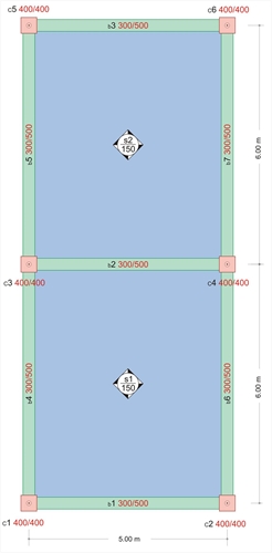 Figure 4.6.4-1: Project <Β_464>
 Figure 4.6.4-1: Project <Β_464>
To determine the critical support moment, both slabs are loaded by the total load:
For the determination of maximum and minimum spam moments, one slab is loaded by the minimum design load gd=g and the other is loaded by the minimum one pd=1.35g+1.50q.
The two following independent loadings p1 and p2 are considered:
g=0.15x25.0+1.5=5.25 kN/m2, thus, for
a) For live load q=2.0 kN/m2
p1=5.25+(0.35x5.25+1.5x2.0)/2= =5.25+2.42=7.67 kN/m2
p2=(0.35g+1.50q)/2=2.42 kN/m2 >
gd=p1-p2=5.25 & pd=p1+p2=10.09 kN/m2
b) For live load q=5.0 kN/m2
p1=5.25+(0.35x5.25+1.5x5.0)/2= =5.25+4.67=9.92 kN/m2,
p2=(0.35g+1.50q)/2=4.67 kN/m2 >
gd=p1-p2=5.25 & pd=p1+p2=14.59 kN/m2
c) For live load q=10.0 kN/m2
p1=5.25+(0.35x5.25+1.5x10.0)/2= =5.25+8.42=13.67 kN/m2
p2=(0.35g+1.50q)/2=8.42 kN/m2 >
gd=p1-p2=5.25 & pd=p1+p2=22.09 kN/m2
Each slab is solved for two types of support by means of proper coefficients for aspect ratio
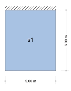 Figure 4.6.4-2
 Figure 4.6.4-2
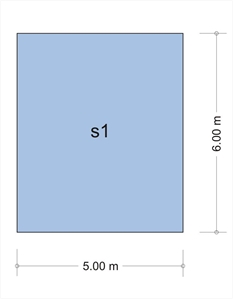 Figure 4.6.4-3
 Figure 4.6.4-3
Table b5.2 for slab s1(one fixed edge and the rest simply supported) gives kx,1=0.453, ky,1=0.547, vx,1=0.738, v y,1=0.631, while table b5.1 for slab s1 (simply supported all four edges) gives kx,2=0.675, ky,2=0.325, vx,2=vy,2=0.610.
The most unfavourable support moment results from the maximum loading pd of both slabs. Since both geometry and loading are symmetric static behaviour of the slabs is identical. Consequently the support moment s1-s2 is equal to the fixity moment of each slab.
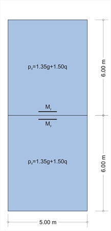 Figure 4.6.4-4
 Figure 4.6.4-4 |
a) For live load q= 2.0 kN/m2
b) For live load q= 5.0 kN/m2
c) For live load q= 10.0 kN/m2
|
The maximum moment of each span results from loading one span with pd and the other span with gd, as shown in the first out of the three following figures. These loadings are equal to pd=p1+p2 and gd=p1-p2 respectively. Analysis is performed by means of equivalent loadings using p1 and p2.
Both 1st equivalent loadings are symmetric, thus both slabs function as fixed on one edge and simply supported on the rest. On the contrary 2nd equivalent loadings are antisymmetric, thus both slabs function as simply supported on all four edges. Consequently the two individual analyses as well as their resultants will be accurate.
|
| | 1st loading of upper slab
| | 2nd loading of upper slab
|
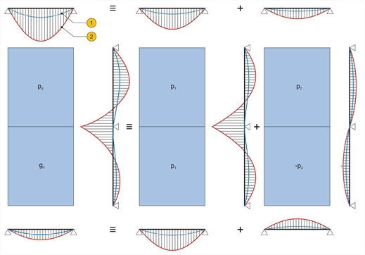 Figure 4.6.4-5
 Figure 4.6.4-5
(1) elastic line, (2) moment diagram
|
| | 1st loading of lower slab
| | 2nd loading of lower slab
|