One-way slabs are those supported on two opposite edges, such as slab s1 in figure of §4.1.
If a one-way slab is supported on more than two edges and its aspect ratio, i.e. the ratio of the larger to the smaller theoretical span, is greater than 2.0 (such as slab s3 in the same figure), it is considered as one-way slab in the principal direction while taking into account the secondary stresses in rest edges.
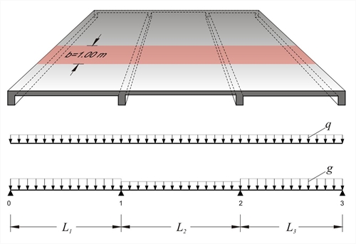
Continuous one-way slabs are analysed considering a frame of continuous bars of rectangular shape cross-section, having width equal to 1.00 m and height equal to the thickness of the slab. The strip loads comprise self-weight, dead and live loads.
a) approximately, by applying all design loads p=1.35g+1.50q (when live load is relatively small)
b) accurately, by taking into account unfavourable loadings.
 Figure 4.5.1-1: Three-span continuous slab
 Figure 4.5.1-1: Three-span continuous slab
The three slabs (previous figure) have L1=4.50 m, h1=180 mm, g1=10.0 kN/m2, q1=2.0 kN/m2, L2=4.00 m, h2=140 mm, g2=5.0 kN/m2, q2=2.0 kN/m2, L3=4.00 m, h3=140 mm, g3=5.0 kN/m2, q3=2.0 kN/m2, where loads g include self-weight. Perform static analysis considering global loading in ultimate limit state.
Design load in each slab is equal to pi=γg·gi+γq·qi=1.35·gi+1.50·qi, thus on 1.00 m wide strip, it is:
p1=1.35x10.0+1.50x2.0=16.5 kN/m
p2=p3=1.35x5.0+1.50x2.0=9.75 kN/m
The three-span continuous slab will be solved through Cross method.
Fundamental design span moments (table b3)
M10=-p1·L12/8=-16.5x4.502/8=-41.8 kNm
M12=M21=-p2·L22/12=-9.75x4.002/12=-13.0 kNm
M23=-p3·L32/8=-9.75x4.002/8=-19.5 kNm
I01=Ic=1.0x0.183/12=4.86x10-4 m4
I12=I23=1.0x0.143/12=2.29x10-4 m4=0.47Ic
Stiffness factors k, distribution indices υ