Effect of live load on the static analysis of one-way slabs The accurate analysis of continuous one way slabs is performed by superimposing the following loadings (unfavourable loadings). Analysis with minimum design dead loads gd,i=1.0gi  Figure 4.5.3.1-1
 Figure 4.5.3.1-1 Maximum and minimum span moments (alternating loading on spans) 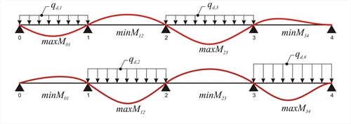 Figure 4.5.3.1-2
 Figure 4.5.3.1-2 Minimum support moments (continuously loading on adjacent spans and alternating with the rest) 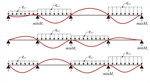 Figure 4.5.3.1-3
 Figure 4.5.3.1-3 Maximum support moments (void loading on adjacent spans and alternating with the rest) The continuous slab shown in the figure, of span length L=5. 00 m and of thickness h=160 mm, is subjected to covering load ge=1.0 kN/m 2 and live load q=5.0 kN/m2. Concrete class C50/60. Calculate the shear forces and bending moments envelopes for the three slabs, in ultimate limit state. Self-weight: go=0.16m·25.0kN/m3= 4.00 kN/m2 Covering load: ge= 1.00 kN/m2 Total dead loads: g= 5.00 kN/m2 Total live loads: q= 5.00 kN/m2 The design dead load for each slab is gd=1.00x5.0=5.0 kN/m and the total design load is pd=γg·g+γ q·q=1.35x5.0+1.50x5.0=14.25 kN/m. I=(b·h3)/12=(1.0x0.163)/12=341x10-6 m4 Modulus of elasticity for concrete C50/60 is equal to E=37.3 GPa. E·I=37.3x10⁹N/m2x341x10-6m4=12.719x106 N·m2 For I10=I12=I23=Ic, stiffness factors k distribution indices υ are:
Due to the symmetry of the structure : u21=0.571 and u23=0.429 Loading 1 : w1=w3=pd=14.25 kN/m, w2=gd=5.0 kN/m (V01,max, M01,max, M12,min, |V32,max|, M23,max)
Principal support moments from table b3 → Μ10=Μ23=-w1·L2/8=-14.25x5.02/8=-44.5 kNm, Μ12=Μ21=-w2·L2/12=-5.0x5.02/12=-10.4 kNm | | | | | | -[+44.5-10.4]×0.429→ -14.6 | | | | +18.8← 0.429×[-(+10.4-44.5-9.8)] | | | | | | | | | | |
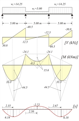 Figure 4.5.3.1-6
 Figure 4.5.3.1-6 V01=14.25x5.0/2-24.1/5.0=35.63-4.82=30.8 kN M01,max=V012/(2·w1)=30.82/(2x14.25)=33.3 kNm w2·L2/8=5.0x5.02/8=15.6 kNm 01: (3) → C1=(-14.25x5.03/24+30.8x5.02/6)=54.1 kN·m2 (4) → (14.25/6)z3-(30.8/2)z2-0+54.1=0 → 2.375z3-15.4z2+54.1=0 gives zmax=2.347 m (2) → y(z)=1/12.719x[(14.25/24)x2.3474-(30.8/6)x2.3473+0x2.3472+54.1x2.347)]> y(2.335)=6.18 mm 12: Due to symmetry of both structure and loading
zmax=2.5 0m C1=(-5.00x5.03/24+12.5x5.02/6-24.1x5.0/2)kN·m2= =-34.2 kN·m 2 (2) → y(z)=1/12.719x[(5.00/24)x2.504-(12.5/6)x2.503+24.1x2.502/2-34.2x2.50) → y(2.50)=-2.72 mm
Loading 2 : w1=w3=gd=5.0 kN/m, w2=pd=14.25 kN/m (V01,min, M01,min, M23,max, |V32,min|, M23,min) Principal support moments from table b3 → Μ10=Μ23=-w1·L2/8=-5x5.02/8=-15.6 kNm, Μ12=Μ21=-w2·L2/12=-14.25x5.02/12=-29.7 kNm | | | | | | -[+15.6-29.7]×0.429→ +6.1 | | | | -7.8←0.429×[-(+29.7-15.6+4.0)] | | | | | | | | | | |
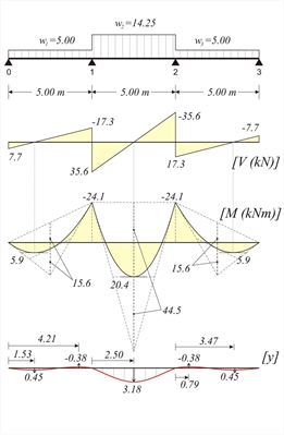 Figure 4.5.3.1-7
 Figure 4.5.3.1-7 V01=5.0x5.0/2-24.1/5.0=12.5-4.8=7.7 kN M01,max=V012/(2·w1)=7.72/(2x5.0)=5.9 kNm w1·L2/8=5x5.02/8=15.6 kNm M12,max=V122/(2·w2)+M1=35.62 /(2x14.25)-24.1=44.5-24.1=20.4 kNm w2·L2/8=14.25x5.02/8=44.5 kNm C1=(-5.00x5.03/24+7.7x5.02/6)kN·m2=6.0 kN·m2 (4) → (5.00/6)z3-(7.7/2)z2-0+6.0=0 → 0.833z3-3.85z2+6.0=0 gives zmax,1=1.53 m και zmax,2=4.21 m (2) → y(z1)=1/12.719x [(5.00/24) x1.534-(7.7/6) x1.533+0x1.532+6.0x1.53) → y(1.53)=0.45 mm (2) → y(z2)=1/12.719x [(5.00/24) x4.214-(7.7/6) x4.213+0x4.212+6.0x4.21) → y(4.21)=-0.39 mm 12: Due to symmetry of both structure and loading
zmax=2.50 m C1=(-14.25x5.03/24+35.6x5.02/6-24.1x5.0/2)kN·m2= =13.9 kN·m 2 (2) → y(z)=1/12.719x[(14.25/24)x2.504-(35.6/6) x2.503+24.1x2.502/2+13.9x2.50) → y(2.50)=3.18 mm
Loading 3 : w1=w2=pd=14.25 kN/m, w3=gd =5.0 kN/m (V12,max, |V10,max|, M1,min) Μ10=-w1·L2/8=-14.25x5.02/8=-44.5 kNm, Μ12=-w2·L 2/12=-14.25x5.02/12=-29.7 kNm M23=-w3·L2/8=-5.0x5.02/8=-15.6 kNm | | | | | | -[+44.5-29.7]×0.429→ -6.4 | | | | -4.3←0.429×[-(+29.7-15.6-4.2)] | | | | | | | | | | |
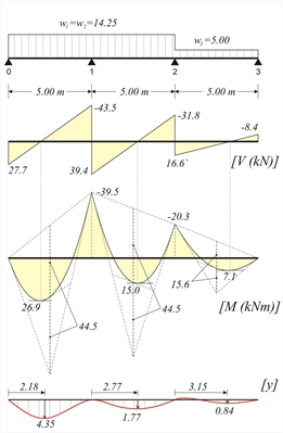 Figure 4.5.3.1-8
 Figure 4.5.3.1-8 V01=14.25x5.0/2-39.5/5.0=35.6-7.9=27.7 kN V12=14.25x5.0/2+(39.5-20.3)/5.0=39.4 kN V23=5.0x5.0/2+20.3/5.0=12.5+4.1=16.6 kN w1·L2/8=14.25x5.02/8=44.5 kNm w3·L2/8=5.0x5.02/8=15.6 kNm C1=(-14.25x5.03/24+27.7x5.02/6)=41.2 kN·m2 (4) → (14.25/6)z3-(27.7/2)z2-0+41.2=0 → 2.375z3-13.85z2+41.2=0 which yields root zmax=2.18 m (2) → y(z)=1/12.719x [(14.25/24) x2.184-(27.7/6) x2.183+0x2.182+41.2x2.18) → y(1.53)=4.35 mm 12: C1=(-14.25x5.03/24+39.4x5.02/6-39.5x5.0/2)kN·m2= (4) → (14.25/6)z3-(39.4/2)z2+39.5z-8.8=0 → 2.375z3-19.70z2+39.5z-8.8=0 which yields root zmax=2.77 m (2) → y(z)=1/12.719x[(14.25/24)x2.774-(39.4/6)x 2.773+39.5x2.772/2-8.8x2.77)> y(2.50)=1.77 mm 23:C1=(-5.00x5.03/24+16.6x5.02/6-0.3x5.0/2)kN·m2= (4) → (5.00/6) z3-(16.6/2) z2+20.3z-7.6=0 → (2) → y(z2)=1/12.719x [(5.00/24) x3.154-(16.6/6) x 3.153+20.3x3.152/2-7.6x3.15)>y(2.50)=0.84 mm
Loading 4 : w1=gd=5.0 kN/m w2=w3=pd=14.25 kN/m This loading is an antisymmetric case of loading 3 with respect to the middle. Envelopes of the results of all loadings: .jpg?bhow=0&w=500&h=500&Str=0) Figure 4.5.3.1-9: Envelopes of shear forces - bending moments - deflections
Figure 4.5.3.1-9: Envelopes of shear forces - bending moments - deflections Figure 4.5.3.1-9: Envelopes of shear forces - bending moments - deflections m1=10.695, mB=-9.025, m2=17.425, p1A=2.315, p1B=-1.635, p2B=1.805 V01,max=pd·L/p1A=14.25x5.0/2.315=30.8 kN V10,min=pd·L/p1B=-14.25x5.0/1.635=-43.6 kN V12,max=pd·L/p2B=14.25x5.0/1.805=39.5 kN M01,max=pd·L2/m1=14.25x5.02/10.695=33.3 kNm M1,min=pd·L2/mB=-14.25x5.02/9.025=-39.5 kNm M12,max=pd·L2/m2=14.25x5.02/17.425=20.4 kNm Analysis using the table is easy, however it fails to provide the negative value of bending moment at middle span.
Analysis using the software (project <B_453-1>) By selecting "Adverse\Slabs" in "Loads" tab of pi-FES dialogue, the software produces the envelopes of shear forces, bending moments and deflections. By the additional choice of "Active module\SLABS" in "Modules" tab, the three envelopes are displayed as follows:  Figure 4.5.3.1-10: Shear force envelope for q=5.0 kN/m2 (Active module\SLABS & Adverse\Slabs)
 Figure 4.5.3.1-10: Shear force envelope for q=5.0 kN/m2 (Active module\SLABS & Adverse\Slabs)
 Figure 4.5.3.1-11: Bending moment envelope for q=5.0 kN/m2 (Active module\SLABS & Adverse\Slabs)
 Figure 4.5.3.1-11: Bending moment envelope for q=5.0 kN/m2 (Active module\SLABS & Adverse\Slabs)
 Figure 4.5.3.1-12: Deflection envelope for q=5.0 kN/m2 (Active module\SLABS & Adverse\Slabs)
 Figure 4.5.3.1-12: Deflection envelope for q=5.0 kN/m2 (Active module\SLABS & Adverse\Slabs)
-
The analysis of continuous slabs under global loading pd=14.25 kN/m gives:
 Figure 4.5.3.1-13: Shear force diagram for p=14.25 kN/m (Active module\SLABS)
 Figure 4.5.3.1-13: Shear force diagram for p=14.25 kN/m (Active module\SLABS)
 Figure 4.5.3.1-14: Bending moment diagram for p=14.25 kN/m (Active module\SLABS)
 Figure 4.5.3.1-14: Bending moment diagram for p=14.25 kN/m (Active module\SLABS)
 Figure 4.5.3.1-15: Deflection envelope for pd=14.25 kN/m (Active module\SLABS)
 Figure 4.5.3.1-15: Deflection envelope for pd=14.25 kN/m (Active module\SLABS)
-
Comparing the results of analysis with global loading and unfavourable loadings, relatively small differences regarding shear forces are noticed, while significant differences regarding span bending moments and deflections are mainly registered at the mid-span. -
· For live load used in common residential design (q=2.0 kN/m2) (project <B_453-2>): pd=γg·g+γq·q=1.35x5.0+1.50x2.0=9.75 kN/m (total design load).
The respective envelopes are illustrated in the following figures:
-
In the case of live load q=2.0 kN/m2, the differences of extreme values are smaller than those of live load q=5.0 kN/m2. Nevertheless for bending moments and deflections the differences remain significant. -
· Working with table b4 is easy, provided equal spans, slab thicknesses and loads are given. Moreover neither possible negative span bending moments or positive support moments are supported.
Simplified method for envelope estimation Unfavourable loadings may not be considered in static analysis of slabs of common buildings, provided that the support and span bending moments are multiplied by an incrementation factor according to the following. -
In case of one way slabs with almost equal spans and load ratio "dead" / "live" = gd/qd = 1.0g / (0.35g + 1.50q) » 1.0or gd/pd = 1.0g / (1.35g+1.50q) » 0.50(valid for most cases of loads used for resintential design), the incrementation factors of bending moments may be taken from following table: | |
| | |
| | |
| | |  Figure 4.5.3.2
 Figure 4.5.3.2 |
-
In case of two-way slabs having almost equal spans, similar increments are valid although reduced by 50%. -
Regarding shear forces, the average increment for all support types is approximately 10%.
|