|
« Frame column stiffness
Multistorey plane frames »
|
Coupled one-storey plane frames As coupled plane frames are defined the plane frames that are connected in such a way that, subject to horizontal forces, they present uniform displacements. The crossbars of the one-bay frames illustrated in the following figure have a practically infinite moment of inertia. Both columns of the first frame have moment of inertia Ι whereas the two columns of the second have Ι and 8Ι respectively. 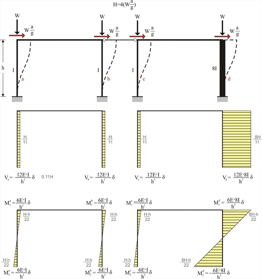 Figure 5.2-1
 Figure 5.2-1 In conclusion, 73% of the seismic shear force is carried by the fourth column. Example 5.2 : Consider that the first three columns have a typical cross-section 400/400 and are 5.0 m high and that the fourth one differs only regarding one of its sides (800 mm instead of 400 mm/400, Ι 800/400 =8 Ι 400/400 ). The seismic acceleration factor is a / g =0.10. H = 4·(0.10·800kN)= 320 kN Va = Vb = Vc =320 ·1 /11=29.1 kN and Vd =320·8/11=232.7 kN Ma1=-Ma2=Mb1=-Mb2= Mc1=-Mc2=29.1·5.0/2=72.8 kNm and Md1=-Md2=232.7·3.0/2=349.1 kNm Ka=Kb=Kc= 12 · EI / h 3 =12 · 32.8 · 109 · Ν /m2 · 21.33 · 10-4m4/(5.03 · m3)=6.72·106 N / m Kd=12E · 8I/h3=8· 6.72·106N/m =53.74 · 106 N/m Σ (K)=11· 6.72·106= 73.89 · 106 N/m Therefore, δ = H / Σ (K)=320·103N/(73.89 · 106 N/m) =4.331 mm
In project <B_520> of the related software, the cross-section of columns C1, C2 and C3 is 400/400 and C4 is 800/400. The height of all columns is 5.0 m. The cross-section of the flanged beam is 250/500/1010/150 and its span is 5.0 m. 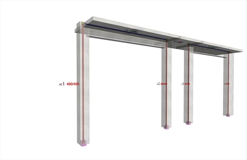 Figure 5.2-2: The structural frame model fully stiffened, project <B_520>
 Figure 5.2-2: The structural frame model fully stiffened, project <B_520>
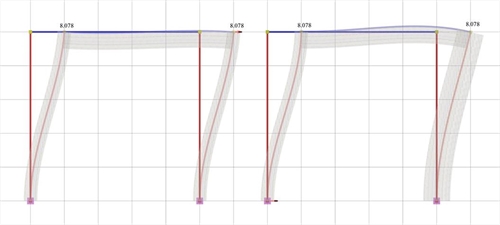 Figure 5.2-3: Elastic line, δ=8.078mm
 Figure 5.2-3: Elastic line, δ=8.078mm | 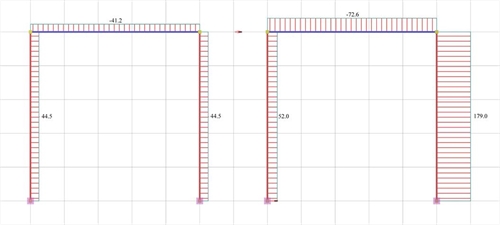 Figure 5.2-4: Shear force diagrams
 Figure 5.2-4: Shear force diagrams | 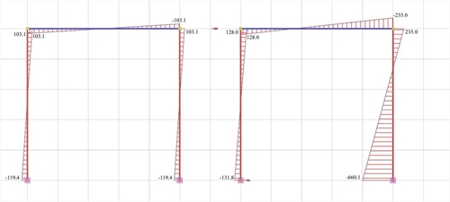 Figure 5.2-5: Bending moment diagrams
 Figure 5.2-5: Bending moment diagrams |
It should be noted that the actual displacement of the crossbar δ=8.078 mm is almost twice the value of the corresponding theoretical value δ=4.331 mm assuming fixed end conditions. This is mainly due to the strong column and the normal beam, which results in a significantly smaller actual stiffness. The actual stiffness of columns C1, C2 Ka=Kb=Va/ δ =44.5·103N/0.008078=5.51·106 kN/m as well as the actual stiffness of column C3 Kc=Vc/ δ =52.0·103N/0.008078m=6.44·106 kN/m differ slightly from the corresponding value (6.72·106 N/m) of the fixed-ended column. On the contrary, the actual stiffness of column C4 Kd=Vd/ δ =179.0·103N/0.008078m=22.16·106 kN/m differs significantly from the corresponding value (53.74·106 N/m) of the fixed-ended column. |
« Frame column stiffness
Multistorey plane frames »
|

|