Thermal insulation of structural elements
When the thermal insulation is embedded inside the exterior or the interior shell of the building and it is independent of the structural frame’s construction, the solution is clear and most of all effective. However, when the thermal insulation is placed upon the exterior or the interior sur-face of the structural frame as part of the total thermal insulation e.g. in buildings with masonry walls, various issues arise. These include thermal bridges and constructional matters regard-ing seismic behavior.
This paragraph deals with the cases where the concrete elements’ thermal insulation is embed-ded in the structural frame. In masonry infills thermal insulation is usually placed inside the ma-sonry walls.
If the energy/bioclimatic design of the building requires the contribution of the structural frame’s heat capacity (this is the common case in residential buildings) then the thermal insulation is placed upon the external surfaces of the structural elements.
In shear walls, columns and beams the thermal insulating boards are placed upon the element’s surface that is on the outer face of the structure. On the other hand, in slabs, most of the times, it is preferable to place them on the bottom side. This is the best solution both from a practical and an energy point of view. However, it may not be ideal for the upper floor slabs.
If the thermal insulating boards are placed on the lower side of the slab and the surface is going to be plastered, it is recommended to place, prior to plastering, a light-weight flexible composite mesh e.g. 10x10 mm glass mesh to prevent plaster cracking especially in the joint areas of the boards and the concrete or the walls.
Placing the thermal insulation boards to the exterior surface of the concrete elements creates one problem; it sets limitations to the proper fitting of bricks in the external masonry walls.
Some of the practices followed when building masonry infills are shown below.
The choice of the most suitable solution depends upon the importance of factors such as: the brick fitting near columns and beams, the formation or not of an edge between the beam and the wall, the weight of the wall, the space they occupy, the cost.
Typical solutions in exterior masonry walls (by using 90x120x190 bricks)
 External blind wall with 2 bull stretchers
 External blind wall with 2 bull stretchers
 External blind wall with 1 bull stretcher and 1 stretcher
 External blind wall with 1 bull stretcher and 1 stretcher
 External blind wall with 2 stretchers
 External blind wall with 2 stretchers
 External wall with sliding frame
External wall with sliding frame
• In areas where the bricks used, have different dimensions from the ones mentioned above, corresponding practices and rules apply.
• The 120 mm thick wall when compared to the one with a thickness equal to 90 mm, has dis-advantages like a higher cost, a larger weight and a 120-90=30 mm limitation of the interior space. On the other hand, it has advantages like the better brick fitting, the higher heat ca-pacity (of the layer towards the inner face) and the possibility to embed electrical piping.
• When it is important for the beam and the masonry to have exactly the same width (no edge formation), apart from the other solutions, a free space may be left between the thermal in-sulation board and the wall.
• When an edge is formed between the beam and the wall, it is preferred to have a large width rather than a small one.
• Based on the type of the electrical installation, we must allow space for the cable piping that will pass through the structural frame or/and the wall.
• A simple way to create channels in the support faces of beams and columns is the use of a board or an extruded polystyrene strip 20 thick and 100 mm long.
• Frequently the real brick dimensions differ from those of standardization. For instance, nine times out of ten, the bricks with nominal dimensions 90x120x190 have real dimensions equal to 85x115x185. On the other hand, the beam’s dimensions are usually correct.
• A typical bond beam reinforcement is: stirrups Ø6/150 and 2 to 4 Ø10 bars (depending on the bond’s width) in both the upper and lower part of the beam. The steel class may be B500A.
• Bond beams’ rebars might end before meeting the columns or they may get anchored inside them.
• The most practical way to anchor the bond beams’ rebars inside the columns is by creating holes to the column sides and implanting starter bars by means of resin adhesives.
Rules for choosing the correct thermal insulation thickness for the structural frame
As far as the thermal insulation efficiency is concerned, the necessary thickness is defined by the corresponding design, however constructional difficulties must be always taken into account.
As far as the proper masonry fitting is concerned, a good solution is to use thermal insulation 30 mm thick in both columns and beams.
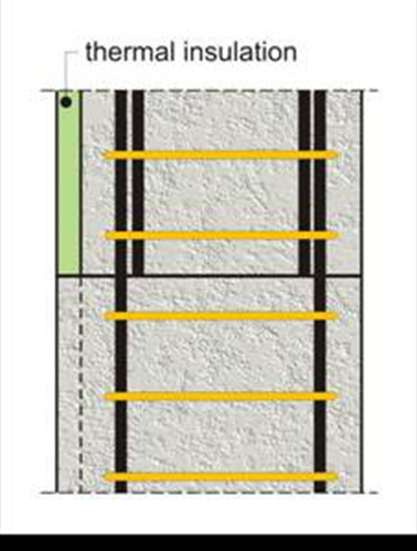
As far as the reinforcement implementation is concerned, it is suggested to use thicker thermal insulation in columns than in beams. As a result, the corner bars of the beams will be anchored, unobstructed, inside the column’s mass, as shown in the vertical beam of the figure, in contrast to the horizontal beam of the same figure, where the edge rebars of the beam have to be bent.
As far as the standardization of the columns’ and beams’ width is concerned, the use of 50 mm thick thermal insulating boards helps both in the increase of the thermal insulation efficiency and in the standardization of the structural elements’ dimensions in integer multiples of 50 mm. However, this creates difficulties in the proper fitting of bricks in external walls. Usage of 90 mm bricks instead of 120 mm eliminates this problem.
Based upon all the above, an optimal technical solution is to use 30 mm thick thermal insulating boards in the columns and 50 mm thick boards in the beams. Moreover, the masonry should be built externally with thickness equal to 120 mm.
When a level does not require thermal insulation e.g. pilotis or basement, extra attention must be paid to the vertical centering of columns so as to avoid having the columns of one floor placed outside the perimeter of the columns that belong to another floor. The next figure shows two columns that have a total cross-section 400/400, however, in the upper floor, the column has a 370/370 cross-section and a thermal insulation board with 30 mm thickness.
These cases are usually met around the perimeter of the building, in pilotis, in basements or in semi-open floors, when the thermal insulation is placed to the outer face of the structures (as it should in most cases). The created problem may be solved with various ways:
1st Solution: Construct a column greater in size and with larger stirrups.
Drawbacks: The drawback in following this solution is the eccentricity of the column’s rebars and the need for bending them up at a large angle, something that entails a high degree of constructional difficulty.
Application: This solution applies to all cases.
2nd Solution : Repositioning of the column’s fixed spot to the edge of the thermal insulation thickness.
Drawbacks: It requires constructional attention and may have possible architectural side-effects due to the formation of an edge.
Application: This solution applies only to superstructures.
3rd Solution: Placement of unreinforced concrete (plain concrete) with thickness equal to the insulation thickness.
Drawbacks: A large concrete thickness with no reinforcement. This problem can be partially solved with the use of surface reinforcement and completely solved with the use of wire mesh when combined with the basement shear walls.
Application: In perimetricl basement column.
An economical and constructionally simple way to efficiently insulate a building and face fewer local problems in the structural frame, is to place the entire insulation at the external face of the building after the completion of the load bearing frame and the masonry walls. That way, a thermal insulating shell, e.g. 50 mm thick is formed circumferentially in all exterior surfaces (concrete and masonry). The placement of this ‘blanket’ is being done after the construction of the structural frame and the masonry walls without thermal insulation. This specific solution, due to the formation of fewer thermal bridges, has the maximum energy efficiency and the advan-tage of that it can be replaced at any time. Like every other innovative technological solution, the above mentioned method is contrary to traditional practices that regarded peripheral walls as monolithic elements, with plaster covering that determined the architectural character of the building. Of course times change and energy changes gradually become dominant, moreover the material science provides new ways of architectural expression that can be adapted to the local conditions of each region.