Wall-equivalent dual type structure 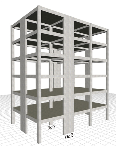 Figure 6.4.2-1: Structure comprising only columns and perimeter walls, project B_642-1
 Figure 6.4.2-1: Structure comprising only columns and perimeter walls, project B_642-1 The structure derives from the frame type structure of §6.4.1 by replacing columns c2, c5, c8 and c11 of cross-section 400/400 with four perimeter walls of cross-section 2000/300. The main mode shapes of the modal analysis of the first case of the wall system are illustrated in the following page (The modes of the other three cases are similar). In the next four pages, the characteristic quantities for all cases are presented. It is extremely useful to compare between the variants of the wall system, but also between the frame and wall systems. General conclusions of the wall system: 1) In all cases, the natural period of the first mode shape is of the order of 0.70 sec. If however the stiffnesses of the elements are taken as being 100% of the elastic, the value of periods is of order of 0.50 sec (see §6.3.3). 2) The wall system behaviour is clearly better than the behaviour of the frame system, particularly when in the presence of a basement with perimeter walls. Modal analysis results of the wall type structure Fixed condition at the ground level (project <Β_642-1>) 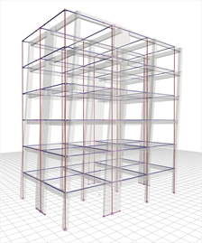 Figure 6.4.2-2: 1st mode:Tx=0.644 sec,
Cx=6.6%, Cy=70.7% Figure 6.4.2-2: 1st mode:Tx=0.644 sec,
Cx=6.6%, Cy=70.7% | 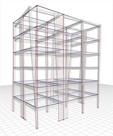 Figure 6.4.2-3: 2nd mode:Tx=0.639 sec,
Cx=70.5%, Cy=6.6% Figure 6.4.2-3: 2nd mode:Tx=0.639 sec,
Cx=70.5%, Cy=6.6% | 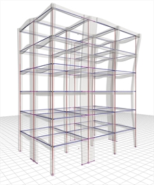 Figure 6.4.2-4: 3rd mode:Tx=0.456 sec,
Cx=0.5%, Cy=0.0% Figure 6.4.2-4: 3rd mode:Tx=0.456 sec,
Cx=0.5%, Cy=0.0% | 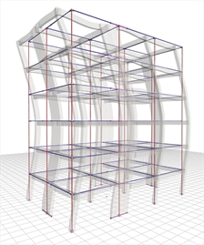 Figure 6.4.2-5: 4th mode:Tx=0.187 sec,
Cx=1.8%, Cy=10.7% Figure 6.4.2-5: 4th mode:Tx=0.187 sec,
Cx=1.8%, Cy=10.7% | In the absence of symmetry in y direction, the fundamental mode shape in x (the 2nd) has also a component in y, meaning that both translational and torsional responses are developed. The sum of the effective modal masses of the 12 first modes amounts to 99.5% and 98.1% of the total mass of the structure in x and in y directions respectively. Case 1: Fixed condition at the ground level (project <Β_642-1>) 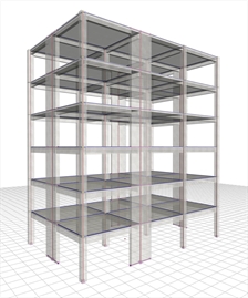 Figure 6.4.2-6: Structure and model.Ductile wall
system in X and Y, with q=3.60 Figure 6.4.2-6: Structure and model.Ductile wall
system in X and Y, with q=3.60 | 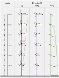 Figure 6.4.2-7: Seismic acceleration-
forces-shear forces.1st fundamental period:
T1X=0.639 sec, participation 70% Figure 6.4.2-7: Seismic acceleration-
forces-shear forces.1st fundamental period:
T1X=0.639 sec, participation 70% | | 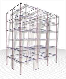 Figure 6.4.2-8: Displacements under seismic
action in x, δmax=16.3 mm Figure 6.4.2-8: Displacements under seismic
action in x, δmax=16.3 mm | Bending moments of ground floor columns |  Figure 6.4.2-9:
Ground floor wall
0c2 (2000/300) Figure 6.4.2-9:
Ground floor wall
0c2 (2000/300) |  Figure 6.4.2-10:
Ground floor column
0c6 (500/500) Figure 6.4.2-10:
Ground floor column
0c6 (500/500) | The behaviour factor of the ductile wall system is found to be q=3.60, a value considered to be the best possible for DCM structures of such structural type. The displacement of the wall type structure is significantly smaller than the one of the frame type structure of the previous paragraph (16.3 mm against 24.5 mm). The bending moment of the first storey, is carried almost exclusively by the walls. Case 2: Foundation with footing beams (project <Β_642-2>) 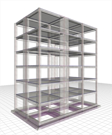 Figure 6.4.2-11: Wall-equivalent dual system in X,
ductile wall system in Y, with q=3.00 Figure 6.4.2-11: Wall-equivalent dual system in X,
ductile wall system in Y, with q=3.00 | 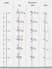 Figure 6.4.2-12: Seismic acceleration-forces-
shear forces.1st fundamental period:
T1X=0.709 sec, participation 75% Figure 6.4.2-12: Seismic acceleration-forces-
shear forces.1st fundamental period:
T1X=0.709 sec, participation 75% | | 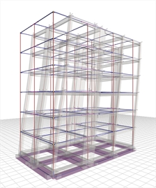 Figure 6.4.2-13: Displacements under
seismic action in x,δmax=21.3 mm Figure 6.4.2-13: Displacements under
seismic action in x,δmax=21.3 mm | Bending moments of ground floor columns |  Figure 6.4.2-14:
Ground floor wall
0c2 (2000/300) Figure 6.4.2-14:
Ground floor wall
0c2 (2000/300) |  Figure 6.4.2-15:
Ground floor column
0c6 (500/500) Figure 6.4.2-15:
Ground floor column
0c6 (500/500) | The cross-sections of the footing beams are not strong enough to carry the high bending moments of the perimeter walls, resulting in the system along y to shift to a wall-equivalent dual system one with overall q=3.00. Moreover, the displacement of this system, along x, is equal to 21.3 mm compared to 25.7 mm of the corresponding frame system. Compared to case 1, the bending moments of the walls are smaller, while of columns are higher. Case 3: Foundation with simple footings (project <Β_642-3>) 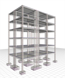 Figure 6.4.2-16: Structure and model.
Wall-equivalent dual system
in X and Y with q=3.00 Figure 6.4.2-16: Structure and model.
Wall-equivalent dual system
in X and Y with q=3.00 | 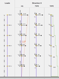 Figure 6.4.2-17: Seismic acceleration-
forces-shear forces.1st fundamental period:
T1X=0.818 sec, participation 78% Figure 6.4.2-17: Seismic acceleration-
forces-shear forces.1st fundamental period:
T1X=0.818 sec, participation 78% | | 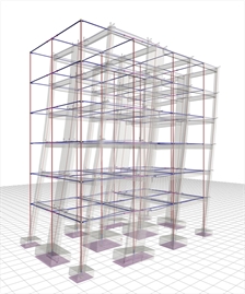 Figure 6.4.2-18: Displacements under seismic
action in x,δmax=23.9 mm Figure 6.4.2-18: Displacements under seismic
action in x,δmax=23.9 mm | Bending moments of ground floor columns |  Figure 6.4.2-19:
Ground floor wall
0c2 (2000/300) Figure 6.4.2-19:
Ground floor wall
0c2 (2000/300) |  Figure 6.4.2-20:
Ground floor column
0c6 (500/500) Figure 6.4.2-20:
Ground floor column
0c6 (500/500) | In both directions the structure functions as a wall-equivalent dual system, due to attenuation of wall behaviour caused by the ground's low ability to oppose rotation. The situation would be considerably improved using strong strap beams. The bending moments of the first storey walls reflect more the frame than the wall behaviour. Case 4: Basement with perimeter walls (project <Β_642-4>) 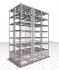 Figure 6.4.2-21: Structure and model.
Ductile wall system in X and Y with q=3.60 Figure 6.4.2-21: Structure and model.
Ductile wall system in X and Y with q=3.60 | 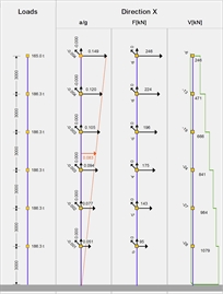 Figure 6.4.2-22: Seismic acceleration-
forces-shear forces.1st fundamental period:
T
1X=0.643 sec, participation 61% Figure 6.4.2-22: Seismic acceleration-
forces-shear forces.1st fundamental period:
T
1X=0.643 sec, participation 61% | | 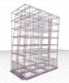 Figure 6.4.2-23: Displacements under
seismic action in x,δmax=16.4 mm Figure 6.4.2-23: Displacements under
seismic action in x,δmax=16.4 mm | Bending moments of ground floor columns |  Figure 6.4.2-24:
Ground floor wall
0c2 (2000/300) Figure 6.4.2-24:
Ground floor wall
0c2 (2000/300) | 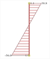 Figure 6.4.2-25:
Ground floor column
0c6 (500/500) Figure 6.4.2-25:
Ground floor column
0c6 (500/500) | The overall behaviour of the structure is much better compared to that of the strong foundation at the ground floor approaching that of the assumed fixed conditions at the base.
|