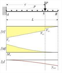
Cantilever is a slab supported on one fixed, such as slab s4 in the figure of §4.1. The fixity on this edge is ensured by another coincident slab, such as slab s2 in the same figure.  Figure 4.4.1
 Figure 4.4.1 Static analysis of cantilevers (as well as one-way slabs) takes into account that loads are applied on 1.00 m wide strips.
The elastic line is calculated, considering separately the uniform load p and the concentrated load P. The left end of the bar is considered to be the origin of coordinate z (local coordinate system xyz, where z is the bar axis). For uniform load p along entire length L :
The basic equation of elastic line is solved in two steps:
Maximum deflection occurs at position z=L and is equal to:
For concentrated load P applied at distance c :
Maximum deflection occurs at position z=L and is equal to:
In the special case where the concentrated load P is applied at the tip of the cantilever, e.g. c=L, maximum deflection is
.
· When the cantilever slab is in continuity with an adjacent slab, its deflection increases by the linear deflection due to the rotation of their common edge.  Figure 4.4.2-1
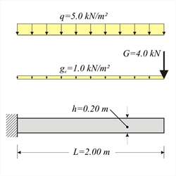
 Figure 4.4.2-1 Cantilever slab with thickness h=200 mm, length L=2.00 m and concrete C40/50, is subjected to covering load gεπ=1.0 kN/m2, live load q=5.0 kN/m2 and concentrated load G=4.0 kN/m applied at the end. Calculate bending moments, shear forces and deflections in ultimate limit state.
 Figure 4.4.2-2
 Figure 4.4.2-2 Consider strip width b=1.00 m. go=γ (b (h=25. 0kN/m3 (1.00m (0.20m=5.0 kN/m ge=1.0kN/m2·1.00m=1.0 kN/m Total distributed dead load:
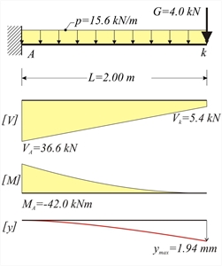
q=5.0kN/m2·1.00m=5.0 kN/m p=γg·g+γq·q=1.35x6.0+1.50x5.0=15.6 kN/m VA=P+p·L=5.4+15.6x2.00=36.6 kN Vk=VA-p·L=36.6-15.6x2.00=5.4 kN MA=-P·L-p·L2/2=-5.4x2.00-15.6x2.002/2=-42.0 kNm For C40/50 it is E=35.2x10⁹ Pa [EC2, 3.1.2] and from volume C' §1.1 a I=b·h3/12=1.00x0.203/12=6.67x10-4 m4 E·I=35.2x10⁹N/m2x6.67x10-4m4=234.8x105 N·m2 Due to uniformly distributed load p:
Due to concentrated load P:
In total: ymax=ymax,1+ymax,2=1.33+0.61=1.94 mm The calculated deflection corresponds to the ultimate limit state. The deflection for serviceability limit state, would result considering the respective serviceability loads with values e.g. ps=1.0g+1.0q=1.0x6.0+1.0x5.0=11.0 kN/m and Ps=1.0G= 1.0x4.0=4.0 kN. Thus, the total deflection would be ys=1.33x(11.0/15.6)+0.61x(4.0/5.4)= 1.39 mm, of course, ignoring creep effects.
|