One-storey space frame with rectangular columns in parallel arrangement The analysis of the one-storey space frame illustrated in the figure, under horizontal seismic force H=90.6 kN is performed by means of four methods: (i) analysis using manual calculations, assuming fixed-ended columns, (ii) analysis using the Excel file, assuming fixed-ended columns, (iii) analysis using the Excel file, assuming columns with k=6, (iv) analysis using software, assuming actual beam and column torsional stiffnesses. 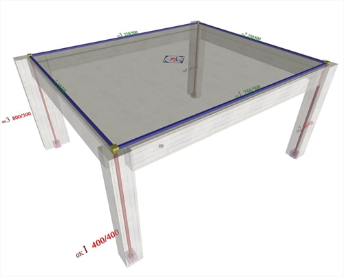 Figure 5.4.5: The structure and the model of the one-storey space frame
 Figure 5.4.5: The structure and the model of the one-storey space frame The names, the loadings, the coordinates and the dimensions of slabs and columns are shown in figure of §5.4.1. The cross-section of beams is 250/500. The concrete class is C30/37 (Ε=32.80 GPa). Analysis using manual calculations, assuming fixed-ended columns (k=12) This method was described via the example presented to all previous paragraphs of this chapter. Analysis using the Excel file, assuming fixed-ended columns (k=12) The related <diaphragm_ortho.xls> spreadsheet is used assuming fixed-ended columns. .jpg?bhow=0&w=500&h=500&Str=0) Figure 5.4.5.2: The results are identical to those of the practical calculations.The torsional stiffness ellipse and the equivalent columns of the structure are illustrated at the end of the spreadsheet.
Figure 5.4.5.2: The results are identical to those of the practical calculations.The torsional stiffness ellipse and the equivalent columns of the structure are illustrated at the end of the spreadsheet. Figure 5.4.5.2: The results are identical to those of the practical calculations.The torsional stiffness ellipse and the equivalent columns of the structure are illustrated at the end of the spreadsheet. Analysis using the Excel file, assuming columns with k=6 The centre of stiffness, the torsional radii and the stress resultants are exactly the same as those of the previous cases, with the exception of deformations, whose relative values, however, remain constant 12/6=2.00. Analysis using software, assuming actual beam and column torsional stiffnesses The analysis may only be performed using the software. The relevant project is <B_545>. The theory for the analytical determination of the diaphragmatic behaviour at a storey level is described in detail in Appendix D. 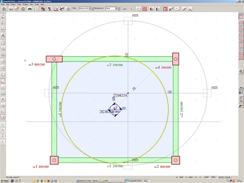 Figure 5.4.5.4-1
 Figure 5.4.5.4-1 The equivalent mass inertial ring is the same as in the two previous methods, since it depends only on the loadings. On the contrary all other quantities are different, as expected. The centre of stiffness CTcoordinates are (3.646, 3.314), whereas the torsional stiffness radii are equal to rx=3.920 m και ry=3.572 m (instead of 3.910 and 3.080 respectively, assuming fixed-ended columns). The cross-section of the equivalent columns is 415/378 (instead of 524/406). All results are listed in details by pressing "Display", "Diaphragm results", "report". These results are presented below, along with the corresponding results (in parentheses) of the 1st and 2nd method considering columns fixed at both ends. Seismic action in X: θXZ= 4.3186·10-5 (4.765·10-5 ) mm, δXXo=0.6840 (0.3375) mm, δXYo=0.0 (0.0) mm Seismic action in Y: θYZ=-3.4940·10-5 (-3.345·10-5) mm, δYXo=0.0 (0.0) mm, δYYo =0.8239 (0.5420) mm |  Figure 5.4.5.4-2
 Figure 5.4.5.4-2 |  Figure 5.4.5.4-3
 Figure 5.4.5.4-3 | 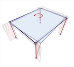 Figure 5.4.5.4-4
 Figure 5.4.5.4-4 | | | Diaphragm restrained
against rotation | (1st Loading) minus (2nd Loading): MCT,X=90.6 · yCM+90.6 · cY | 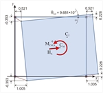 Figure 5.4.5.4-5
 Figure 5.4.5.4-5 | 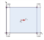 Figure 5.4.5.4-6
 Figure 5.4.5.4-6 | 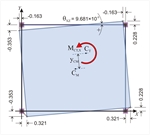 Figure 5.4.5.4-7
 Figure 5.4.5.4-7 | The displacements of each point i δ X,i , δ Y,i and the rotation angle of the diaphragm | Each point of the diaphragm (therefore the CT as well ) has the same principal displacements δ XXo =0.684 mm , δ XYo =0. | The diaphragm develops only a rotation θ XZ about CT. The displacements of each point i due to rotation are equal to: δ Xt,i = δ X,i - δ XXo , δ Yt,i = δ Y,i - δ XYo . | Calculation of the diaphragmatic behaviour (continued) 1st (and only) floor level  Figure 5.4.5.4-8
 Figure 5.4.5.4-8 | 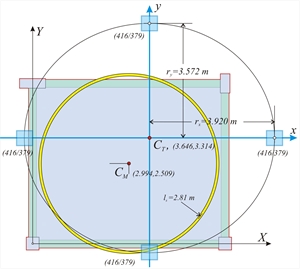 Figure 5.4.5.4-10
 Figure 5.4.5.4-10 | Diaphragm restrained against rotaion | 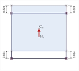 Figure 5.4.5.4-9
 Figure 5.4.5.4-9 | The diaphragm is not rotated, but only translated in parallel to the axes X, Y. Each point of the diaphragm (therefore and the CT) has the same principal displacement: δ YXo =0, δ YYo =0.824 mm. The 3 rd analysis completes the necessary series of analyses for the determination of all diaphragm data. | tan(2a)=2 δ XYo /( δ XXo - δ YYo )=0.0 à 2a=0° à a=0° Kxx=Hx/ δ xxo =90.6·103m/0.684·10-3m=132.5·106 N/m Kyy=Hy/ δ yyo =90.6·103m/0.824·10-3m=110.0·106 N/m MCT,X=90.6 · yCM+90.6 · cY=90.6 ·(3.316-2.500)+90.6·1.0=164.5 kNm K θ = MCT,X/ θ XZ =164.5/9.681 ·10-5=17.0·105kNm rx=√K θ /Kyy=√17.0·108N/m/110.0·106N/m=3.931m ry=√K θ /Kxx=√17.0·108N/m/132.5·106N/m=3.582 m |
|