|
« The effect of torsional stiffness on indirect beam-to-beam supports
Modelling slabs using bar and two-dimensional finite elements »
|
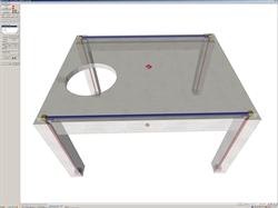
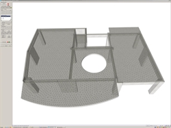
Modelling frames using two-dimensional finite elements The analysis methods presented in previous paragraphs, form the principle rules in static and dynamic analysis of earthquake resistant structures. They are based on general assumptions allowing separate analysis of slabs and frames. Slabs can be analyzed separately, provided that particular geometrical rules and secondary reinforcement placement rules are followed, thus balancing the inevitable effect of frames on slabs. Frames (beams-columns) can be modelled with bar finite elements, taking into consideration the slabs effect, firstly by using the effective flange width and secondly by assuming diaphragmatic restraints on all slab nodes. Referring to columns and especially to shear walls, the actual geometry of column and beam bars is considered by using rigid bodies. The design of most significant construction works has been performed using the above modeling scheme, whereas it stands as the principle rule for structural design according to EC2, EC8 and any other international regulations. Nowadays, two-dimensional finite elements are widely used since, in general, they provide more accurate results. Due to certain limitations imposed by the dynamic spectral analysis, in countries with zero or low seismic actions, two-dimensional finite elements have been established even for common buildings, whereas in highly seismic regions bar finite elements are mainly used. In dynamic spectral analysis, bar finite elements provide sufficient accuracy for the calculation of design seismic accelerations. The combination of the two methods, called the mixed model, is considered to be successful and is based on forming two consecutive models of the same structure: (a) The first one takes into account bar finite elements for beams, columns and shear walls using rigid bodies technique, while the seismic behaviour of slabs is accounted through diaphragmatic restraining. The seismic design accelerations derive from the response spectrum analysis of the structure (as indicated in §3.3.2). In reinforced concrete buildings, the human factor (despite good intentions and despite the level of knowledge, conception and attention) affects chaotically the structural quality in different aspects. This phenomenon is particularly intense when seismic requirements arise, materials are non-homogeneous and construction is non-industrialized. The various regulations,e.g. the Eurocodes, having full knowledge of the human factor, define appropriate safety factors and rules for calculation as well as construction methods. EC2 and EC8 allow the use of conservative and tested calculation methods on one hand and the use of advanced calculation methods on the other hand, forming the future of calculation approaches and regulation codes. The transition from the traditional tested calculation practices to the future development of more accurate calculation methods should be gradual and ensuring that the future absorbs the experience of the traditional practices.  Figure 3.3.5-1: The slab with a hole is modelled either accurately as a diaphragm using finite elements, either approximately using the appropriate assumptions, e.g. ignoring the diaphragmatic function
 Figure 3.3.5-1: The slab with a hole is modelled either accurately as a diaphragm using finite elements, either approximately using the appropriate assumptions, e.g. ignoring the diaphragmatic function |  Figure 3.3.5-2: The diaphragmatic function is ensured and not affected by this hole despite its size
Figure 3.3.5-2: The diaphragmatic function is ensured and not affected by this hole despite its size
|
This book contributes to the smooth transition from the traditional calculation methods to the more accurate future methods while dealing with both of them.
|
« The effect of torsional stiffness on indirect beam-to-beam supports
Modelling slabs using bar and two-dimensional finite elements »
|

|