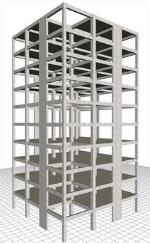
 Figure 6.3.1-1: Ten-storey building of
mixed system. Diaphragmatic and non-diaphragmatic nodes. Project <B_547-2> Figure 6.3.1-1: Ten-storey building of
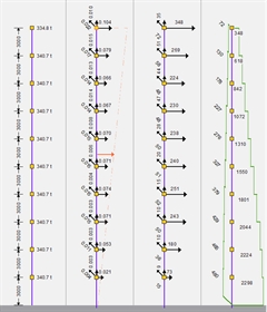
mixed system. Diaphragmatic and non-diaphragmatic nodes. Project <B_547-2> | Seismic action in X direction | | | | | |  Figure 6.3.1-2: Page from the software report.Distribution of seismic
accelerations-forces-shear forces Figure 6.3.1-2: Page from the software report.Distribution of seismic
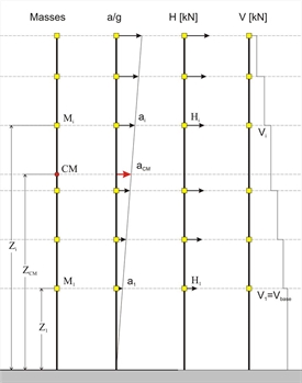
accelerations-forces-shear forces | The nodal seismic forces HXX, HXY και HXZ are obtained from the nodal seismic accelerations multiplied by the nodal mass. The seismic accelerations and forces due to a horizontal component (X and Y) of the seismic action are not only developed in the direction considered but also in the other horizontal direction and the vertical. Seismic forces, shear forces, bending moments Seismic accelerations are quantities calculated directly by superimposing modal responses through CQC method. The CQC method always produces quantities with positive sign, as it is the square root of a sum of modal quantities. In this respect, only the comparison of their absolute values has a meaning. If the sign is required e.g. to calculate the seismic forces and then the position of the centres of stiffness, then a good choice would be to use the sign of the fundamental mode shape, e.g. of that with the maximum effective mass participation factor (effective modal mass). In the related software two combination methods are used for the calculation of the stress resultants: 1st method : CQC of seismic accelerations/forces According to this method, masses are assumed at the centres of mass of diaphragms and at the end nodes if diaphragms are not present. The seismicaccelerations ai,j are calculated using CQC at discreet positions i of the structure (i.e. diaphragms centres of mass and nodes not belonging to a diaphragm) due to j component of the seismicaction. The corresponding seismic forces are thus obtained by the expression Hi,j= ai,j · mi at thevarious discreet positions i of the structure under the horizontal and vertical components of the seismic action j= Χ, j=Υ και j=Ζ. The stress resultants for each combination are calculated, using classic structural analysis, based on the seismic forces. This method is used by default by the software (but it can be changed by the user), having the advantage that the signs of the stress resultants are compatible to those of the classic structural analysis, which is the base and the reference of EC8 and EC2. 2nd method : CQC of all resultants According to this method, all the seismic quantities are calculated using CQC, i.e. forces, displacements, bending moments, shear forces with sign that of the corresponding modal quantity of the fundamental mode shape. Modal response spectrum analysis assuming masses placed in the centres of diaphragms is required in both methods. In the second method four additional dynamic analyses are required assuming masses placed at the four points of accidental eccentricities (see §6.5). Of course, the accidental eccentricities actually refer to the relative displacements of the centres of mass and stiffness and it may be more logical to consider their influence on the seismic forces of the first method. The seismic forces are not quantities calculated by the analysis but a derivative one, obtained by multiplying the seismic acceleration by the diaphragm mass, or by the mass of the beams and columns framing into the joints that do not belong to the diaphragms. Seismic shear forces are also derivative quantities as, for each storey, they are the sum of seismic forces in X and Y direction of the overlying stories. The sum of columns and walls shear forces of each storey is calculated by the analysis and should be equal to the seismic forces of the storey considered. This is a simple and efficient check for any software. Internal forces and moments of each structural member are calculated through classic structural analysis using the seismic forces of the diaphragmatic nodes, or/and of the nodes not belonging to any diaphragm. Approximate method for the calculation of seismic accelerations [EC8, §4.3.3.2.2] For educational reasons and for verification of the order of magnitude of the dynamic analysis results, the base shear and the distribution of seismic accelerations and seismic forces of a structure may be calculated by a simple approximate method. This method may be applied to buildings with heights up to 40 m, meeting the criteria for regularity in elevation whose response is not significantly affected by contributions of modes higher than the fundamental mode in each principal direction. Step 1 : assessment of the fundamental natural periods of vibration of the building T1,X, T1,Y. -
H is the building height, in m, from the foundation or from the level of the rigid basement top. -
Ct is frame system factor - For the i direction frame system, Ct,i=0.075 - For the i direction wall system, Ct,i=0.050  Figure 6.3.3
 Figure 6.3.3 | Step 2 : assessment of the design acceleration aCM,i of the centre of mass of the building. Sd(T1,i) is the design acceleration corresponding to the natural period of vibration, based on the §6.1.6. λ is the correction factor for the effective mass participation in 1stmode, taken equal to 0.85 for buildings having more than two storeys and T1≤2Tc, while 1.0 otherwise. Step 3 : calculation of accelerations at each level of the building. The assumption of the triangular distribution is adopted according to the expression aj=(Zj/ZCM) · aCM where ZCM=Σ(Mj · Zj )/Σ(Mj) | Cracking and plasticity effects According to the Eurocodes [EC8, §4.3.1(7)], structural elements may be considered as cracked, thus their stiffness properties may be taken to be equal to 50% of the corresponding stiffness of the uncracked elements. When the stiffnesses of columns, walls and beams change, the dynamic behaviour of structures i.e. natural periods, effective masses, seismic accelerations and eventually seismic forces, displacements and stress resultants, are affected. Beyond the dynamic response differences due to the decreased stiffnesses, the static behaviour of the structures is also affected. Considering the same seismic forces when stiffnesses are taken as half (0.50E · I) of the elastic (E · I) ones, then flexural displacements double, but shear and axial displacements remain intact. Therefore the total displacements (flexural + shear + axial) are less than double. In predominantly frame type structures (where bending effect dominates) the total displacements are roughly less than double, while in mainly wall structures (where shear effect is significant) the downward deviation from double can be significant. The development of deformations is continued even after the cracking of columns, walls and beams, in the actual plastic region. The increase rate of the plastic deformations depends on the ductility of the elements, i.e. their capacity to exhibit post-yield deformations. In case of reinforced concrete, ductility is accomplished by using dense and well closed stirrups and suitable longitudinal reinforcement placed in the perimeter (see volume Α' §1.4.2). The final displacements are the plastic displacements equal to the displacements of the cracked elements multiplied by the behaviour factor q taken under consideration in the base shear calculation (see also §5.4.7, exercise 2). The determination of the maximum plastic displacement of a building is necessary in cases of an existing or eventual adjacent structure, e.g. as in attached buildings, to provide for an adequate seismic joint [EC8, §4.4.2.7 & §4.3.4], required to protect them from earthquake-induced pounding
|