|
« Diaphragmatic behaviour
Centre of stiffness and elastic displacements of the diaphragm »
|
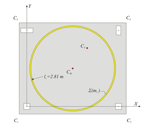
Centre of mass and radius of gyration The inertial behaviour of a diaphragm having a mass Σ(mi) is idealised by a ring of equivalent inertial massdistribution. The ring has a total mass Σ(mi), its centre is theCentre of Mass CM and its radius theRadius of Gyration ls.  Figure 5.4.2: The centre of mass CM and the equivalent mass inertial ring with radius of gyration ls
 Figure 5.4.2: The centre of mass CM and the equivalent mass inertial ring with radius of gyration ls The coordinates of the centre of mass CM of a diaphragm consisting of many mass points, linearly distributed, and surface masses linearly distributed derive from the expressions: The radius of gyration ls of the diaphragm with respect to the centre of mass CM derives from the expression: where Χi and Υi are the coordinates of each mass point mi of the diaphragm, whereas Ipi is the polar moment of inertia of each mass mi with respect to the centre of mass CM. According to the strength of materials, the polar moment of inertia of a mass m, whose centre is located at distance L from the centre of mass CM of the diaphragm, depends on the distribution of the mass: - For a point mass: Ip=m·L2
- For a mass linearly distributed along a segment of length l: Ip=m· (l2/12 + L2)
- For a surface distributed mass in a rectangular shape of dimensions b,l: Ip=m· [(b2+l2)/12 + L2]
- For a surface distributed mass in a triangular shape or a circular segment: the equivalent principal moment of inertia in respect to the centre of mass of this segment is calculated and the Steiner term m·L2 is added.
In large floor plans, the radius of inertia can be calculated only from the reaction forces of the beams on the floor columns, while in case that the particular linear loads (e.g. of the walls) are distributed uniformly throughout the floor, the radius of inertia is calculated using the formula where L x, L y are the dimensions of the floor plan. Radius of gyration : [g=10 m/sec2, therefore force F=1 kN corresponds to mass m=0.1 t.] Slab: m1=6.0m ·5.0m·0.71t/m2=21.3 t b1=6.0 m, l1=5.0 m, L1=0.0 m → Ip1=21.3t ·(6.02+5.02)m2/12=108.3 t·m2 Beam connecting C1-C2: m2=6m·1.0t/m=6.0 t, l2=6.0 m, L2=2.5 m → Ip2=6.0· (62/12+2.52)=55.5 t·m2 Beam connecting C3-C4: likewise m3=6.0 t, Ip2=55.5 t·m2 Beam connecting C1-C3: m4=5.0m·1.0t/m=5.0 t, l4=5.0 m, L4=3.0 m → Ip4=5.0· (5.02/12+3.02)=55.4 t·m2 Beam connecting C2-C4 likewise m5=5.0 t, Ip5=55.4 t · m2 Columns: m6=0.1 ·(4.00+4.00+6.0+4.5)=1.85 t, L6=√ (3.02+2.52)=3.905 m → Ip6=1.85 ·3.9052=28.2 t·m2.
|
« Diaphragmatic behaviour
Centre of stiffness and elastic displacements of the diaphragm »
|

|