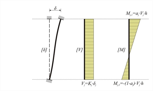
 Figure 5.1.5: Frame column stiffness in direction j (j=x, y):
 Figure 5.1.5: Frame column stiffness in direction j (j=x, y):
In the general case of a frame column, the stiffness K in a direction j is equal to:
kjis the stiffness factor and it generally varies between 0 and 12. In the same direction there is also the moment distribution factor aj varying between 0.0 and 1.0.
Always Mj,1 - Mj,2 = Vj· h
The stiffness reduction factor due to shear effect is:
The stiffness assessment is required for the understanding of the Floor Diaphragmatic Behaviour that follows in §5.4.
Frames could comprise either columns only, called "frame systems" or columns and walls called "dual systems". These two types of frame systems will be considered in the following paragraphs.
One-storey frame structural systems
In project <B_5151a> of the related software, the cross-section of all columns is 400/400 and their height 3.0 m. The cross-section of the flanged beams is 300/500/1300/150 and their span 6.0 m. The seismic horizontal force is equal to 50 kN.
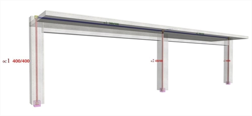 Figure 5.1.5.1-1: The structural frame model without rigid bodies but fully stiffened, project <B_5151a>
 Figure 5.1.5.1-1: The structural frame model without rigid bodies but fully stiffened, project <B_5151a>
The parameter values for this modelling are identical to the corresponding ones of the example 5.1.3 except that in this case force X is equal to 50.
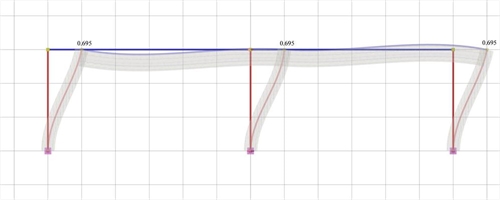 Figure 5.1.5.1-2: Elastic line, δ=0.695 mm
 Figure 5.1.5.1-2: Elastic line, δ=0.695 mm |
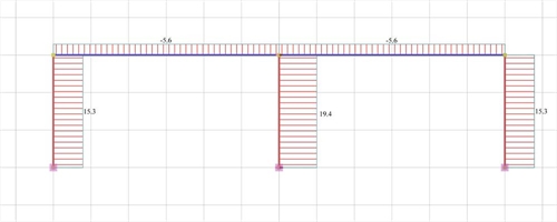 Figure 5.1.5.1-3: Shear force diagrams
 Figure 5.1.5.1-3: Shear force diagrams |
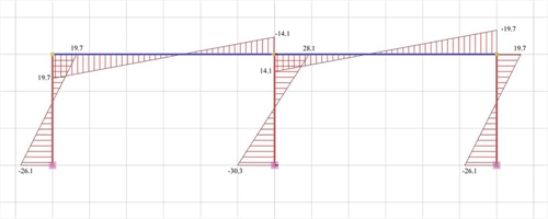 Figure 5.1.5.1-4: Bending moment diagrams
 Figure 5.1.5.1-4: Bending moment diagrams |
Analysis results of project <B_5151a> with full beam and column stiffness (graphical representation in the related software)
The actual stiffness of the C1, C3 is:
K1=K3=V1/ δ =15.3·103N/0.000695m=22.01·106 kN/m
against 31.10·106 N/m of the fixed-ended column.
Therefore the stiffness factor is:
while the moment distribution factor a, i.e. the portion of the moment V · h applied on the column top is:
The actual stiffness of column C2 is:
K2=V2/ δ =19.4·103N/0.0006955m=27.91·106 kN/m
against 31.10·106 N/m of the fixed-ended column. The respective factors are:
Although the middle column has the same cross-section with the other ones, its stiffness is higher since two frame beams resist its bending.
Project <B_5151b> derives from project <B_5151a> by adding foundation beams with cross-section 300/800/1500/400 at level -0.80 m.
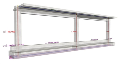 Figure 5.1.5.1-5: The structural frame model fully stiffened, project <B_5151b>
 Figure 5.1.5.1-5: The structural frame model fully stiffened, project <B_5151b>
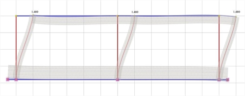 Figure 5.1.5.1-6: Elastic line, δ=1.480 mm
 Figure 5.1.5.1-6: Elastic line, δ=1.480 mm |
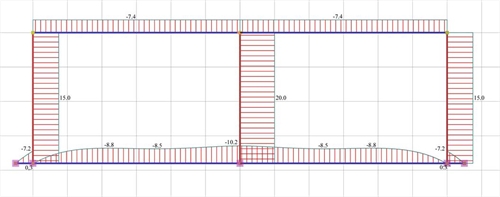 Figure 5.1.5.1-7: Shear force diagrams
 Figure 5.1.5.1-7: Shear force diagrams |
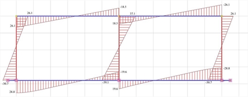 Figure 5.1.5.1-8: Bending moment diagrams
 Figure 5.1.5.1-8: Bending moment diagrams |
Analysis results of project <B_5151b> with actual beam and column stiffness (graphical representation in the related software)
The actual stiffness of the C1, C3 is:
K1=K3=V1/ δ =15.0·103N/0.001480m=10.14·106 kN/m
against K=12·EI/h3=12·(32.8·109·Ν/m)2·(21.33·10-4m4)/(3.803·m3)=15.30·106 N/m of the fixed-ended column, which in this case has height 3.80 m.
The stiffness factor results to be:
while the moment distribution factor a, i.e. the portion of the moment V·h applied at the column top is:
The actual stiffness of column C2 is:
K2=V2/ δ =20.0·103N/0.001480m=13.51·106 kN/m
against 15.30·106 N/m of the fixed-ended column. The corresponding factors are:
k2=12·13.51/15.30=10.6 and a=178.0/(178.0+187.8)=0.49
The foundation nodes are placed close to the ground since, besides the members modelling columns and the foundation beams, another "member" also exists modelling the soil. Special importance should be attached to this "member". The differences in column stiffnesses are mainly due to their different mixed height. The mixed column height is equal to the free height of the foundation floor increased by the excavation depth. The excavation depth is usually equal to the foundation height.
- This analysis has been carried-out considering an average soil type. In case of a more elastic soil, the stiffness reduction is higher.
- In case individual footings without beams are used in the foundation, the stiffnesses become smaller and the displacements of the crossbars considerably higher.
- A basement above the foundation results in higher stiffnesses and smaller displacements.
One-storey dual structural systems
In project <B_5152a> of the related software, the structure comprises two end columns and a wall in the middle with cross-sections 400/400 and 2000/300 respectively. Their height is 3.0 m. The cross-section of the flanged beams is 300/500/1300/150 and their span is 6.0 m. The horizontal seismic force is 50 kN.
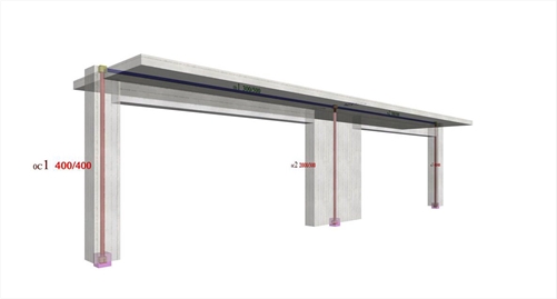 Figure 5.1.5.2-1: One-storey dual type structure comprising two columns and a wall (project <B_5152a>)
 Figure 5.1.5.2-1: One-storey dual type structure comprising two columns and a wall (project <B_5152a>)
The parameter values for this modelling are the same as in the frame systems of the previous paragraph.
 Figure 5.1.5.2-2: Elastic line, δ=0.059 mm
 Figure 5.1.5.2-2: Elastic line, δ=0.059 mm |
 Figure 5.1.5.2-3: Shear force diagrams
 Figure 5.1.5.2-3: Shear force diagrams |
 Figure 5.1.5.2-4: Bending moment diagrams
 Figure 5.1.5.2-4: Bending moment diagrams |
Analysis results of project <B_5152a> with actual beam and column stiffnesses (graphical representation in the related software)
The actual stiffness of columns C1, C3 is:
K1=K3=V1/ δ =1.6·103N/0.0000589m=27.16·106 kN/m
against 31.10·106 N/m of the fixed-ended column.
k1=k3=12·27.16/31.10=10.5
while the moment distribution factor a, i.e. the portion of the moment V·h applied to the column top, is:
The actual stiffness of column C2 is:
K2=V2/ δ =46.8·103N/0.0000589m=794.6·106 kN/m
against K=12·EI/h3=12·(32.8·109·Ν/m2)·(0.3·2.03/12m4)/(3.03·m3)=2915.56·106 N/ m of the fixed-ended column. The corresponding factors are:
k2=12·794.6/2915.56=3.3 and a=7.7/(7.7+132.6)=0.05
Therefore, the wall behaves almost like one-end-fixed (with k=3.0 and a=0.0), while columns almost like fixed-ended (with k=12 and a=0.50). If shear effect is taken into account, the crossbar displacement is δ=0.075 mm i.e. significantly higher. If rigid bodies are also taken into account, the crossbar displacement is δ=0.070 mm i.e. it is reduced.
Project <B_5152b> derives from project <B_5152a> by adding at level -0.80 m flanged foundation beams with cross-section 300/800/1500/400.
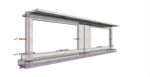 Figure 5.1.5.2-5: The structural frame with the actual stiffness in project <B_5152b>
 Figure 5.1.5.2-5: The structural frame with the actual stiffness in project <B_5152b>
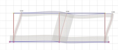 Figure 5.1.5.2-6: Elastic line, δ=0.382mm
 Figure 5.1.5.2-6: Elastic line, δ=0.382mm |
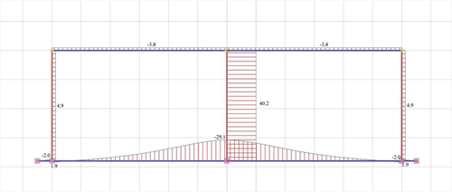 Figure 5.1.5.2-7: Shear force diagrams
 Figure 5.1.5.2-7: Shear force diagrams |
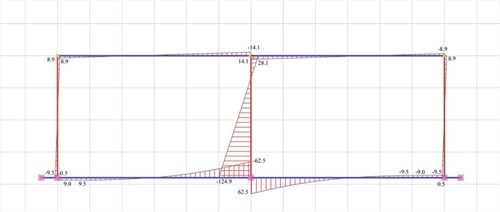 Figure 5.1.5.2-8: Bending moment diagrams
 Figure 5.1.5.2-8: Bending moment diagrams |
Analysis results of project <B_5152b> with actual beam and column stiffness (graphical representation in the related software)
The actual stiffness of columns C1, C3 is:
K1=K3=V1/ δ =4.9·103N/0.000382m=12.83·106 kN/m
against K=12·EI/h3=12·(32.8·109·Ν/m2)·(21.33· 10-4m4)/(3.83·m3)=15.30·106 N/m of the fixed- ended column, which in this case has a height of 3.80 m.
Therefore the stiffness factor is:
k1=k3=12·12.83/15.30=10.1
while the moment distribution factor a is:
The actual stiffness of column C2 is:
K2=V2/ δ =40.2·103N/0.000382m=105.24·106 kN/m
against K=12·EI/h3=12·(32.8 ·109·Ν/m2)·(0.3·2.03 /12) m4/(3.83·m3)=1434.61·106 N/m of the fixed- ended column.
The corresponding factors are:
k2=12·105.24/1434.61=0.88 and a=28.1/(28.1+124.9)=0.18
It should be noted that the foundation affects significantly the wall stiffness. The increase of the crossbar displacements is also notable. If shear effect is taken into account, the crossbar displacement is δ=0.399 mm, i.e. slightly higher. If rigid bodies are also taken into account, this displacement is reduced almost in half δ=0.176 mm.
- This analysis has been performed for an average type of soil. The stiffness reduction is higher for a more elastic soil.
- A basement above the foundation, results in columns with higher stiffnesses values.