|
« Frame model
Analysis of frames »
|
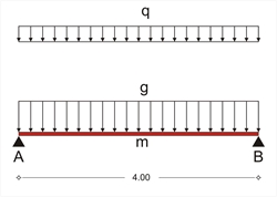
 Figure 3.3.2: The equivalent bar, hinged at both ends,
of the slab strip Figure 3.3.2: The equivalent bar, hinged at both ends,
of the slab strip In this example, slab s1 is hinged at both ends with width h=170 mm, and span l=4.00 m. Τhe design stress resultants, result from the slab's self-weight and covering loads and a live load q=5.00 kN/m2. The analysis models the slab as a strip of width 1.00 m. The self-weight of concrete is 25.0 kN/m3 therefore: Self-weight: go=0.17mx1.00mx25.00kN/m3 =4.25 kN/m Covering: ge=1.00mx1.00kN/m2 =1.00 kN/m Total dead loads: g =5.25 kN/m Total live loads: q=1.00mx5.00kN/m2 =5.00 kN/m The design combination for the ultimate limit state derives from the design load psd=γg·g+γq·q which in this case is: psd=1.35g+1.50q=1.35x5.25+1.50x5.0=14.59 kN/m, therefore, the stress resultants used for the slab design, derive from the expressions: V Ad =-V Bd =14.59x(4.00/2)=29.18 kN M md =14.59x(4.002/8)=29.18 kNm
|
« Frame model
Analysis of frames »
|

|