- The differences between values of stress resultants of Slab results and FEM results
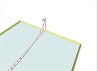 Figure 4.2.4-1: Slab results: "Moments" and "Show Values" Average value on 1.0 m wide strip, of bending moment My in the middle of the edge
 Figure 4.2.4-1: Slab results: "Moments" and "Show Values" Average value on 1.0 m wide strip, of bending moment My in the middle of the edge | 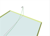 Figure 4.2.4-2: FEM results: "M22" (My) and "Diagrams" Point value of bending moment My in the middle of the edge
 Figure 4.2.4-2: FEM results: "M22" (My) and "Diagrams" Point value of bending moment My in the middle of the edge | 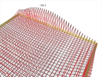 Figure 4.2.4-3: Slab results: "Moments" with "Details" per 0.1 m Distribution of average values on 1.0 m wide strip, of bending moments [My] along the edge
 Figure 4.2.4-3: Slab results: "Moments" with "Details" per 0.1 m Distribution of average values on 1.0 m wide strip, of bending moments [My] along the edge | 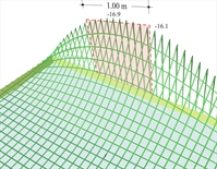 Figure 4.2.4-4: FEM results: "M22" (My) with "Details" per 0.1m Distribution of bending moments [My] along the edge
 Figure 4.2.4-4: FEM results: "M22" (My) with "Details" per 0.1m Distribution of bending moments [My] along the edge |
In order to comprehend the differences between Slab results and FEM results, slab S1 of example 1 is used. The moment value Ms (Slab Results) in the middle of the common edge of slabs S1-S2 is -16.1 kNm. This value is derived by integrating the diagram of FEM results on a rectangle of width 1.0 m, at the middle of the common edge, having peak moment -16.9 kNm. Notice that at the end of the edge under consideration, the bending moment derived from Slab results is not equal to zero, as the one derived from FEM results. This is because the end moment represents the average value the 1.0 m wide area. The slab design is performed using the values from Slab results, which, in general, are considerably smaller at peak points. The integration width 1.0 m can change through software parameters to e.g. 0.5 m. - The precise value of stress resultants at slab supports
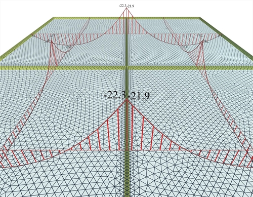 Figure 4.2.4-5: The support moment is unique for both slabs, however the values on either side differ slightly due to different mesh geometry.
 Figure 4.2.4-5: The support moment is unique for both slabs, however the values on either side differ slightly due to different mesh geometry. The mesh parameters are identical for all 4 slabs of the project <B_411-1>: "Overall size" = 0.10 m, "Perimeter size" = 0.05 m. However, due to different mesh geometry, there are slight differences between the values of stress resultants in either side of their common edges. The value of the support moment Ms can be considered as either the average value, i.e. Ms=-(22.3+21.9)/2=-22.1 kNm , or the maximum value, i.e. Ms=-22.3 kNm. - The effect of finite element size on accuracy of results, problem size, computational time and memory required
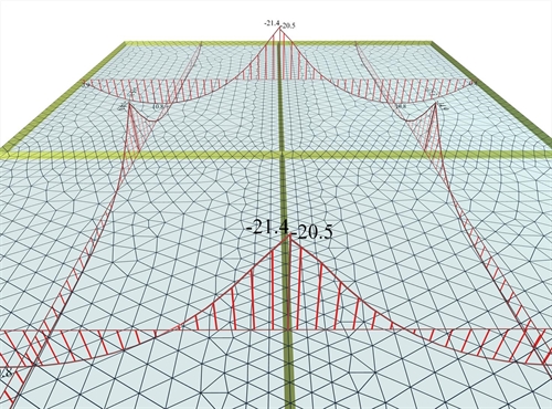 Figure 4.2.4-6: As much as the number of the finite elements is reduced the accuracy of the results diminishes.
 Figure 4.2.4-6: As much as the number of the finite elements is reduced the accuracy of the results diminishes. Τhe finite element mesh of the same project <B_411-1> has emerged from the following parameters: "Overall size" = 0.25 m, "Perimeter size" = 0.15 m. The average value of the support moment is Ms=-(21.4+20.5)/2=-21.0 kNm compared to the previous value of -22.1 kNm, which is a significant difference. The denser mesh the better accuracy achieved, but at the same time the number of calculations, the amount of memory and time is increased substantially. The computer processor plays an important role, since many algorithms have the ability of parallel processing in their available cores. In the previous examples the report of the related software gives: Project <B_411-1> (adverse - module "SLABS"), dense meshing: 29,632 triangular elements, 16,418 nodes, 1201 linear members, system of 98,506 equations, memory 665 MB, time 10 sec, FPS=60 [*] NoteFPS are the Frames Per Second of the 3D display, i.e. is the refresh rate of the screen and it is the size that counts the smoothness of the 4D virtual reality. Τhe human eye perceives the motion as real when FPS>25. NoteFPS are the Frames Per Second of the 3D display, i.e. is the refresh rate of the screen and it is the size that counts the smoothness of the 4D virtual reality. Τhe human eye perceives the motion as real when FPS>25. Project <B_411-1> (adverse - module "SLABS"), sparse meshing: 1,930 triangular elements, 1,287 nodes, 241 linear members, system of 7,722 equations, memory 100 MB, time 1 sec, FPS=60 The above measurements were performed on a PC 64 bit, 3.0 GHz, with 4# cells, graphic card GeForce GTX 550 Ti 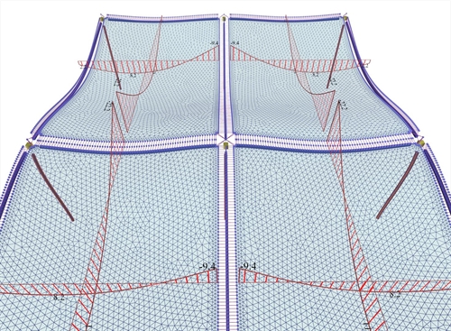 Figure 4.2.4-7: In module 'BUILDING', the interaction of the slabs with the structure is taken into account resulting from point to point more or less favourable stresses compared to the module 'SLABS'
 Figure 4.2.4-7: In module 'BUILDING', the interaction of the slabs with the structure is taken into account resulting from point to point more or less favourable stresses compared to the module 'SLABS' As explained in detail in chapter 3 and appendix Α, the influence of beams and columns on the behaviour of a building is very important. In this example, the bending moment of the slabs S1-S2 is significantly smaller compared to the 'SLABS' module. The support moment, in this module, is provided directly on the side faces of the beams, wherein the detailing takes place. However, the peak moment in the middle of the support (in the middle of the beam) is much higher. Project <B_411-1> : (Adverse\Slabs - Active module\BUILDING), dense meshing gives: 26672 triangular elements, 16,417 nodes, 3856 linear members, system of 98,502 equations, memory 680 MB, time 12 sec, FPS=56 - Multi-storey buildings and envelopes
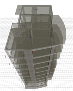 Figure 4.2.4-8: The real structure in 3D
 Figure 4.2.4-8: The real structure in 3D 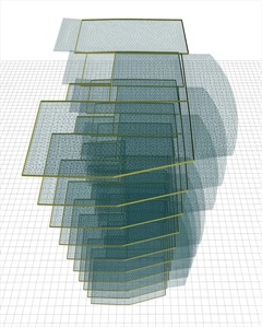 Figure 4.2.4-9: The structure's model in 3D
 Figure 4.2.4-9: The structure's model in 3D For the slab analysis, the unfavourable loadings are created per floor, i.e. loading of any floor slab has no effect on slabs of other floors. In "SLABS" module this effect is obvious while in "BUILDING" module is rather insignificant. Project <Japan5>, running only in the professional version, consists of 10 floors with an area of 200 m2. The following measurements are obtained using the following meshing parameters: "Overall size" = 0.20 m, "Perimeter size" = 0.10 m. Adverse\Slabs - Active module\"SLABS": 134,292 triangular elements, 77,131 nodes, 6,507 linear members, 462,786 equations, memory 3.8 GB, time 125 sec, FPS=37 Adverse\Slabs - Active module\ "BUILDING" 183,217 triangular elements, 120,239 nodes, 34,727 linear members, 721,434 equations, memory 5.3 GB, time 209 sec, FPS=28
|